


TROUBLESHOOTING LBI-38988
Rev. B 29
TROUBLESHOOTING
The hardware used in the GETC is extremely reliable,
making component failure the unlikely cause of most
problems. The most common causes of problems are
programming errors and interface connections.
Use the following guidelines when troubleshooting a
GETC on site:
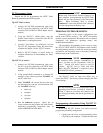
1. Verify the operation of front panel LEDs. This
can be done by performing the Operational
Checkout and verifying the LED indications.
GETCs using 349A9607 Group 4 software may
also indicate the specific cause of the failure, refer
to Failure Mode.
2. Verify that all cables are properly connected and
secure.
3. Verify the GETC’s personality is properly
programmed for the specific application. Refer to
TQ-3357, PC Programmer and SRN1060 (SRN
1024 if using 19A705595G8 software).
4. Verify the Turbo Board is properly configured if
applicable. Refer to LBI-38822 and SRN 1062.
5. If you suspect that the GETC has failed, replace
the it with a known good unit properly configured
for this application. Recheck all software and
personality parameters and checkout the GETC’s
operation. If the GETC functions properly, repair
or replace the malfunctioning GETC according to
the instructions in LBI-38894.
FAILURE MODE
With the introduction of 349A9607 Group 4 software,
the GETC is able to indicate a specific failure via the front
panel LEDs. Prior to group 4 software, a failure is
indicated by incorrect LEDs, but the GETC did not indicate
the root cause. The failure modes listed in Table 14
describe the LED displays and their corresponding failure
mode interpretation.
In all 3 failure modes, the channel is completely taken
out of service. This allows the System Manager in Fully
Trunked systems to display a channel failure. In Trunked
Failsoft, the channel is removed from service to avoid using
the bad channel.
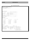
CHANNEL ACTIVITY LOGGER
Another diagnostic feature introduced with the
349A9607 Group 4 software is the Channel Activity
Logger. This feature allows the GETC to supply
information about what it sees from its inputs: the RF
receiver, phone line receiver, station interface I/O.
Additionally, the GETC can supply internal event
information about what the GETC is doing. For example,
if the GETC tries to train its Rockwell modem, it will print
a message “MODEM TRAINING STARTED,” and when
the modem becomes trained, it will print “MODEM
TRAINING COMPLETED.” In General, the information
supplied by the Channel Activity Logger is EDACS specific
and in some cases may need technical assistance for
interpretation. For detailed instructions on using the
Channel Activity Logger, refer to SRN1060 and PC
Programmer TQ-3357 V4.03 (or later).
IN CASE OF DIFFICULTY
If you are unable to resolve a problem to your
satisfaction, then contact the Ericsson Technical Assistance
Center (TAC) at 1-800-528-7711 (outside USA, 804-528-
7711).
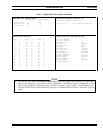
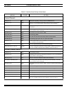
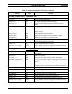
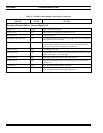
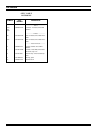
Table 14 - Failure Modes
LED DISPLAY FAILURE MODE POSSIBLE FAILURE CAUSE
LED 7 (only ) - Flashing
Flashing rate = 1 second
Quick synthesizer reload after every 5 flashes
of LED 7 (quick flash of LEDs 3, 4, and 5)
GETC is unable to cause a
synthesizer lock.
Bad synthesizer, Bad 10V Station Power
Supply, incorrect operation of MASTER
III Station Module, J26 Incorrect.
LED 6 (only) - Flashing
Flashing rate = 1 second
GETC has detected a PA Low
Power Alarm condition.
Bad PA, incorrect adjustment of R141,
uncalibrated Power Sensor.
LED 6 & 7 (only) - Flashing simultaneously
Flashing rate = 1 second
GETC has detected failure of
Turbo Board.
Turbo Board switches not in operational
position (toward rear of GETC), wrong
turbo software, bad turbo card.