


03-TM-0037 REV 13
Page 13 of 24
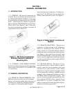
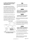
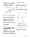
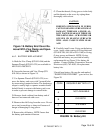
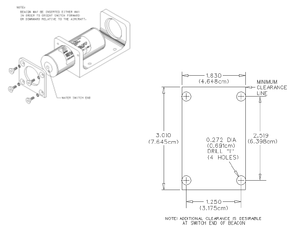
Figure 10. Installation of N30A29
Series Mounting Kit and Beacon
D. Insert the beacon into the mounting cradle
with the water switch facing forward and/or
downward with reference to the aircraft. Rotate
the beacon in the mount so that the beacon
replacement date can be read. See Figure 10.
E. Screw securing plate in place with the set of
furnished screws and washers. Tighten until the
securing plate makes contact with the frame in
the area of the screws, with approximately 15 to
20 inch-pounds torque.
F. Perform the Operational Test outlined in
Section IV.
2.9. INSTALLATION PROCEDURES FOR
THE DK130/DK140 AND THE N30A21A
MOUNTING KIT.
2.9.1. GENERAL. Space limitations sometimes
require the use of the strap-type N30A21A Mount-
ing Kit. Where a choice exists, horizontal mount-
ing with switch forward is best. If vertical mount-
ing is employed, mount switch down to reduce
accumulation of grease, dirt, and water on the
switch end of the beacon.
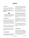
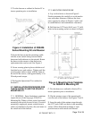
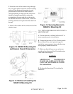
Figure 11. Mounting Hole Template
for N30A21A Mounting Kit
C. Test the beacon as outlined in Section IV to
insure operation prior to installation.
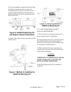
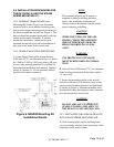
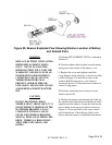
D. Slip the retainer straps of the mounting kit
over the ends of the beacon. See Figures 13 and
14.
2.9.2. MOUNTING PROCEDURE.
A. Lay out four holes as shown in Figure 11. Po-
sition mounting kit carefully to avoid
interferencewith other structures. Observe the
clearances required as shown in Figures 11 and
12, and in established tool and maintenance clear-
ances.
B. Drill the four 0.272 inch (0.691 cm) (“I” drill)
holes in the mounting surface as shown in Figure
11.
B. Make sure that the beacon case and water
switch, are free of grease or film. If in doubt,
wipe clean with mild detergent
C. Test the beacon as outlined in Section IV to
insure operation prior to installation.