


03-TM-0037 REV 13
Page 14 of 24
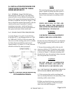
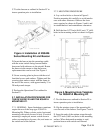
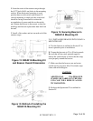
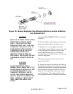
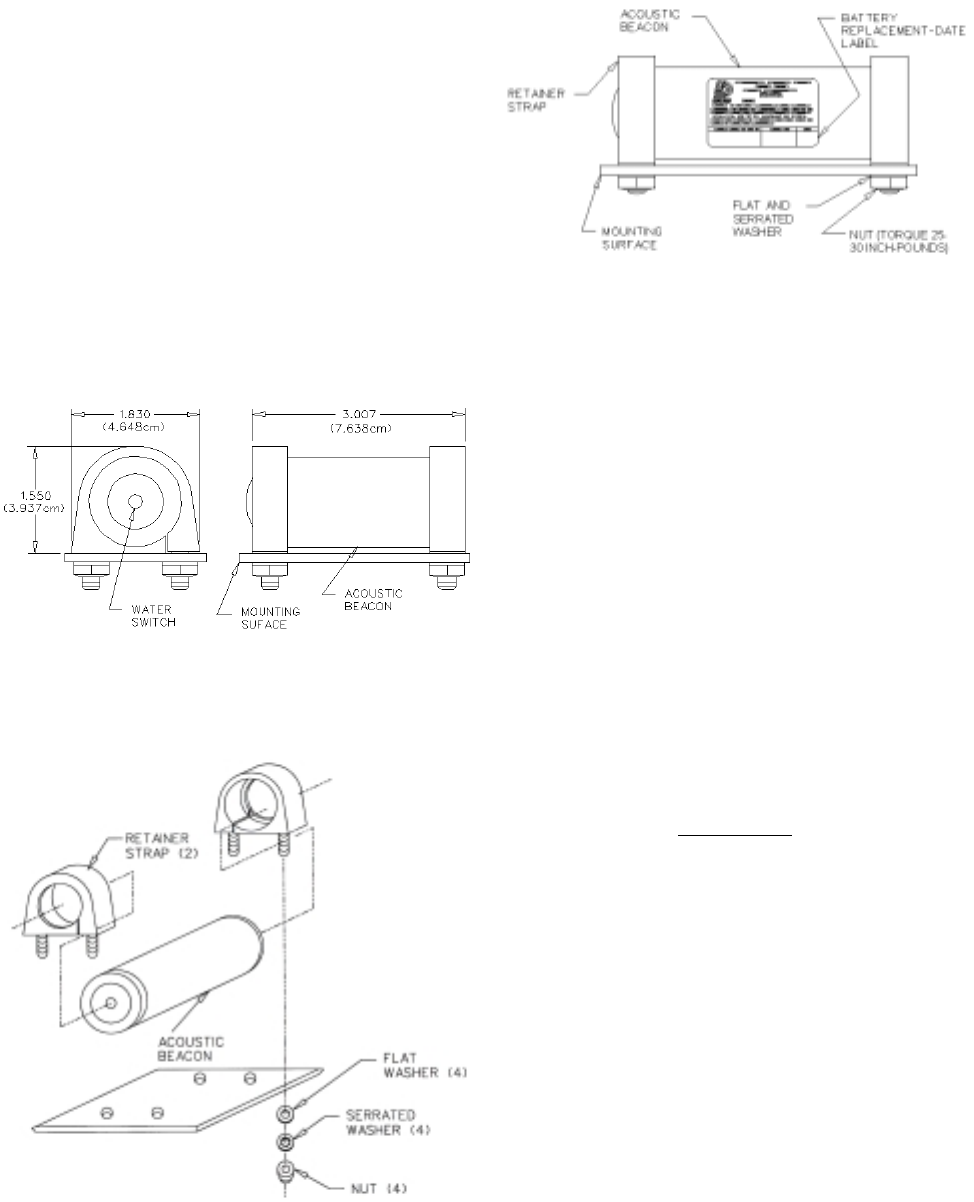
Figure 12. N30A21A Mounting Kit
and Beacon Overall Dimensions
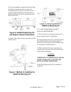
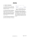
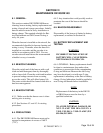
Figure 13. Method of Installing the
N30A21A Mounting Kit
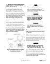
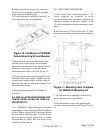
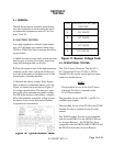
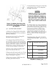
Figure 14. Securing Beacon In
N30A21A Mounting Kit
2.9.3. INSTALLING BEACON INTO N30A21A
MOUNTING KIT.
A. Test the beacon as outlined in Section IV to
insure operation prior to installation.
B. Torque the four nuts to 25 to 30 inch-pounds.
Be sure that all four studs protrude approxi-
mately the same amount to insure that the strap
seats properly around the beacon.
C. Make sure that the beacon case and water
switch are free of grease film. If in doubt, wipe
clean with mild detergent.
CAUTION
ADDITIONAL UNAPPROVED
STAMPS OR LABELS ON THE BEA-
CON CASE WILL REDUCE ACOUS-
TIC RADIATION.
D. Perform the Operational Test outlined in
Section IV.
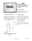
E. Insert the ends of the retainer straps through
the 0.272 inch (0.691 cm) holes in the mounting
surface. When horizontal mounting is used,
position beacon with switch end forward. If
vertical mounting is employed, the switch end
should be facing downwards to reduce the
accumulation of grease and dirt on the switch
end. Rotate the beacon in the mount, so that the
markings and beacon replacement date label can
be read.
F. Install a flat washer and nut on each end of the
retainer straps.