


Lotus Service Notes Section EMN
Page 7
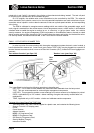
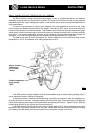
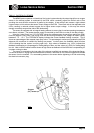
EMN.3 - THROTTLE CABLE ADJUSTMENT
Before adjusting the cable, first check that the pedal end of the cable is correctly located, and that the
cable is correctly routed with no sharp bends or entrapment. Do not attempt to adjust the throttle cable or idle
speed by means of the stop screw on the throttle body, which should not be disturbed.
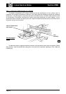
The throttle cable and associated components must be adjusted in a specific sequence to ensure full and
correct throttle operation without cable strain. The procedure is detailed in sub-section JH.8 but may be
summarised as follows:
- Adjust the pedal upstop for a pedal height 30mm below brake and clutch pedals.
- Adjust the ball jointed pull rod connecting to the pedal to achieve a gap of 20mm between outer cable
abutment and multiplier lever pivotting link.
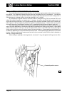
- Adjust the locknuts at the engine end of the outer cable to allow a small amount of free play to accommo-
date temperature change effects.
- Adjust the pedal downstop so that full travel of the throttle butterfly can just be achieved without allowing
the cable to be strained.
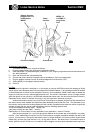
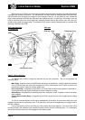
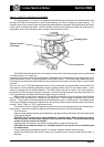
EMN.4 - ELECTRONIC CONTROL MODULE (ECM)
The ECM is an electronic processor mounted on a panel either at the left hand side of the rear luggage
compartment (pre 'bootbox') or at the rear of the engine compartment (with 'bootbox'). The immobilisation
feature of the vehicle security system results in the ECMs for engine management and security being match
coded, such that the engine module must recognise a coded signal from the security module before the unit
becomes operative.
The engine ECM is an adaptive unit which 'learns' the optimum setting of the idle air control valve, and
the fuelling offset required to achieve the correct exhaust oxygen content for a particular engine relative to its
wear and performance characteristics. This feature speeds the response of the system, and minimises the
time spent adjusting to changed operating conditions.
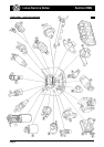
A summary of the sensors supplying inputs to the ECM, and the components to which the ECM supplies
output control, follows:
Inputs Outputs
Crankshaft position Ignition coil
Manifold absolute pressure Fuel injectors
Engine coolant temperature Idle air control valve
Intake air temperature Fuel pump relay
Exhaust oxygen content ECM Diagnostic connector
Throttle position Oxygen sensor heater relay
Camshaft position (VVC) VVC control solenoids
Oil temperature (VVC) Main relay
Diagnostic input Radiator cooling fans
Battery supply
Starter signal
Earth supply
Vehicle security signal
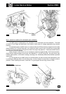
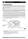
Note that the ECM on 'bootbox' cars built between September '98 and February '00 was originally mounted
on the front side of the composite bootbox. In order to improve electromagnetic shielding, a steel mounting
plate was introduced to secure and earth the ECM directly to the rear subframe. All such cars should be retro-
fitted with this steel mounting bracket.
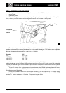
If a replacement engine ECM is fitted (or security 5AS module), the Lotus Check tool must be used to
match the engine management and security modules. VVC models may use the MEMS 2J card for this
operation (see EMN.2), whereas standard cars must use the security 5AS card and the password system (see
section MN.2.