


Lotus Service Notes Section EMN
Page 24
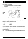
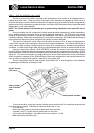
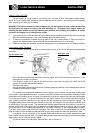
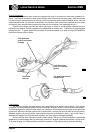
8. To remove an injector from the rail, unplug the harness connector, remove the clip, and withdraw the
injector from the rail. Discard the two 'O' rings.
9. Before re-fitting the injectors and rail, clean the injector recesses in the rail and inlet manifold, and fit
each injector with 2 new 'O' rings lubricated with silicone grease. Fit the injectors into the rail, and retain
with the spring clip.
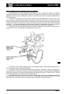
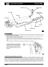
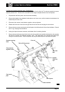
10. Carefully insert each of the injectors into its inlet manifold bore, and retain the rail with the two fixing bolts,
tightened to 9 Nm.
11. Continue re-assembly in the reverse order to disassembly, tightening the inlet pipe to rail screws to 4 Nm.
EMN.17 - IGNITION SYSTEM
Standard Engines
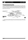
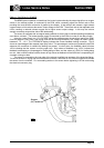
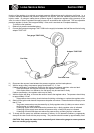
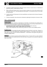
The ignition system comprises a single ignition coil mounted on the RH side of the cylinder block, a
distributor driven from the rear end of the inlet camshaft, and low tension control circuitry within the ECM. The
ECM controls ignition timing based on inputs from the following sensors:
- Crankshaft position sensor; supplies engine speed and crankshaft position information.
- Manifold absolute pressure sensor; supplies engine load information.
- Engine coolant temperature sensor; allows timing variations for optimum cold driveability and idle.
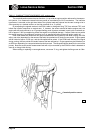
Idle Speed Control
The main control over engine idle speed is attained by the use of the idle air control valve. However, for
rapid response, and to inhibit stalling when additional loads are placed on, or removed from the engine, the
ECM varies the ignition timing to achieve idle stabilisation. An observation of idle ignition timing will see a
constantly changing reading.
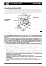
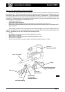
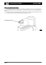
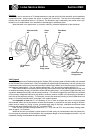
Ignition Coil
The ignition coil has a low primary winding resistance (0.63 to 0.77 ohms at 20°C) in order to allow full
high tension output to be reached faster than normal, and make coil operation more consistent throughout the
engine speed range.
em203
Ignition coil