


Lotus Service Notes Section EMN
Page 3
EMN.1 - INTRODUCTION
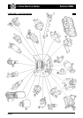
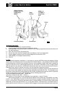
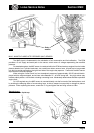
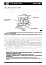
Key to Component Location Diagram
1. Fuel pump 14. Cam angle sensor (VVC only)
2. Engine coolant temperature (ECT) sensor 15. Idle air control (IAC) valve
3. Water temperature gauge sender (vertical) 16. Throttle postion (TP) sensor
4. Crankshaft position sensor 17. Throttle body
5. Oxygen sensor 18. Relay module
6. Intake air temperature (IAT) sensor 19. Data link connector (DLC)
7. Oil temperature sensor (VVC only) 20. Electronic control module (ECM)
8. VVC control solenoids 21. Inertia switch
9. Fuel injector 22. Vehicle speed sensor
10. Fuel pressure regulator valve 23. Fuel filter
11. Fuel rail 24. Distributor (std. only)
12. Manifold air pressure (MAP) sensor (VVC only) 25. Evaporative emissions canister
13. Ignition coil (std. and VVC shown)
The 1.8 K Series engine fitted to the Elise is equipped with a Modular Engine Management System
(MEMS), version '1.9' for the standard engine, and version '2J' for the VVC engine, abbreviated to 'MEMS 1.9'
or 'MEMS 2J'. Both versions use a single electronic control module (ECM) to control both the fuel injection and
ignition systems, and base the control strategy on engine speed/air density measurement. Engine speed data
is derived from a flywheel sensor, with air density calculated from manifold air pressure and manifold air
temperature signals.
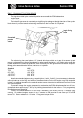
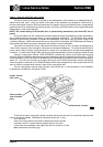
The engine features a throttle body housing a single throttle butterfly valve, with position sensor, feeding
into an intake plenum chamber with four individual intake tracts, each of which is fitted with a fuel injector
positioned to spray fuel onto the back of the intake valves. Standard engines use a lightweight moulded plastic
plenum/manifold, whereas on VVC engines, the manifold is alloy. Fuel delivery quantity is controlled by the
length of time (pulse width) for which the solenoid operated injectors are energised, with the injectors of
standard engines grouped in pairs, 1 with 4, and 2 with 3, whereas the VVC engine uses a fully sequential
strategy with individual control of each injector.
The air/fuel ratio is calculated by the ECM using a three dimensional map to provide a basic fuelling
specification under various operating conditions. In order to refine the fuel delivery and cater for special
conditions, various types of compensation are provided:
- Cranking enrichment; During cranking, when engine speed is below about 400 rpm, the injection pulse
width is increased, dependent on coolant temperature, to aid starting.
- After start enrichment; Immediately after starting, the pulse width is increased, but decays at a rate
dependent on coolant temperature.
- Acceleration enrichment; Signals received from the throttle position and MAP sensors which indicate
acceleration is demanded, will prompt additional fuel for smooth and ready response.
- Overrun fuel cut-off; At normal running temperature, when the throttle is closed and engine speed is
above about 2,000 rpm, indicating engine overrun, the fuel supply is shut off to enhance economy and
reduce emissions.
- Overspeed fuel cut-off; At a specified engine speed, the injectors are cut off in order to protect the engine
from overspeeding.
- Oxygen sensor feedback; By measuring the oxygen content of the exhaust gas, any adjustment neces-
sary to maintain the air/fuel ratio to that required by the catalytic converter for optimum conversion
efficiency may be computed by the ECM. An electrically heated oxygen sensor is used to ensure its
speedy attainment of working temperature after a cold start.
- Battery voltage correction; The ECM senses battery voltage, and applies a correction factor to take
account of any variation in fuel delivery due to battery voltage fluctuation.
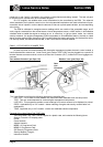
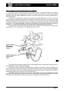
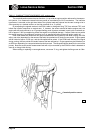
An idle air control valve mounted on the throttle body, is used to regulate the amount of air by-passing the
throttle plate, and hence control engine idle speed.
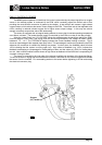
Two types of ignition system are used, both controlled by the ECM. Standard engines use a single
ignition coil mounted on the right hand side of the cylinder block, and a distributor driven from the rear end of
the inlet camshaft. VVC engines use a distributorless ignition system (DIS) which employs a pair of double
ended ignition coils and a 'waste spark' system whereby each coil fires two spark plugs simultaneously (1