


Lotus Service Notes Section EMN
Page 19
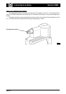
EMN.16 - FUEL SYSTEM
The fuel system is a high pressure recirculating type, using an 'in tank' submerged 3-stage impeller
pump, an in line canister filter, a common fuel rail supplying all four injectors, and a fuel pressure regulating
valve controlling the return line to the tank.
WARNING: The fuel line between pump and injector rail, and the injector rail itself, contain pressurised
fuel both when the engine is running, and after switching off. This feature aids engine starting by
reducing the time needed to build up operating fuel pressure, and inhibiting the formation of vapour
pockets in the supply line of a stopped hot engine.
i) To minimise the risk of fire and personal injury, relieve the fuel system pressure before servicing the fuel
rail or any related component. See Fuel Pressure Relief Procedure below.
ii) To reduce the possibility of sparks occurring when a fuel line is disconnected, or when fuel vapour is
present, the negative battery cable should be disconnected before work is commenced.
iii) When fuel lines are disconnected, absorb any escaping fuel in an absorbent cloth and dispose of safely.
Fuel Pressure Relief Procedure
This procedure should be used prior to disconnecting any part of the fuel line except the unpressurised
return line.
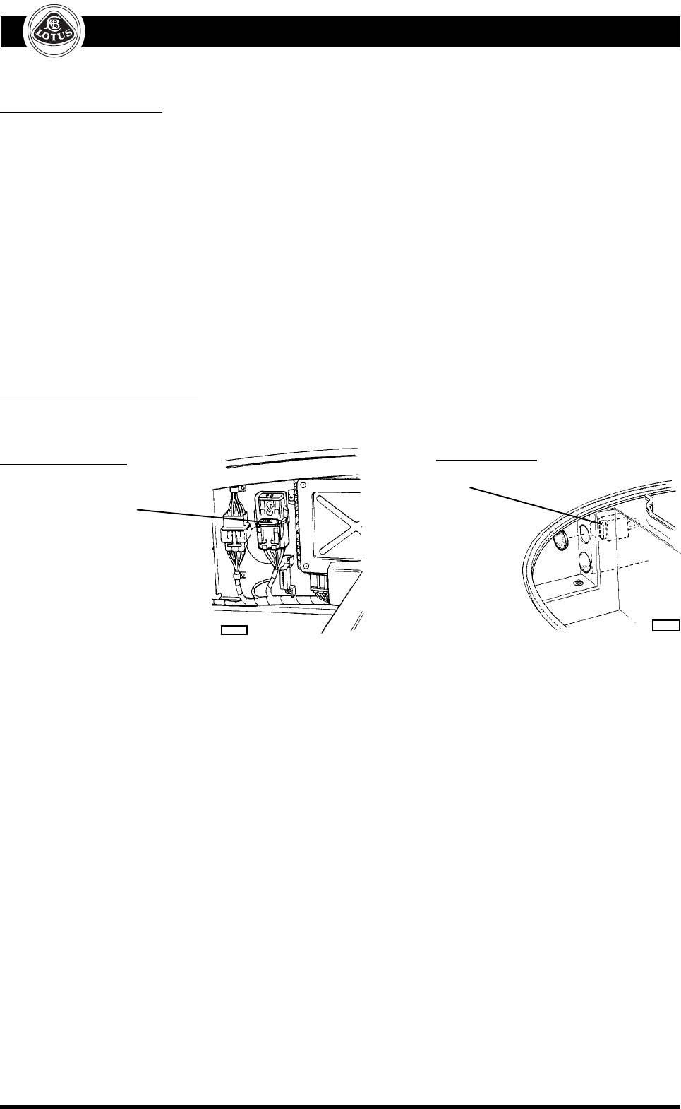
- Pull out the fuel pump 20A fuse (see above), start the engine, and run until it stops from starvation. Crank
the engine for a further 10 seconds.
- If the engine is a non-runner, pull out the fuel pump fuse, and crank the engine for a total time of 60
seconds to minimise residual fuel pressure.
- Disconnect the battery.
- Use a shop towel to absorb the small amount of pressurised fuel remaining as a fuel feed pipe connection
is released, and dispose of safely.
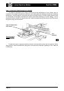
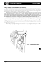
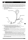
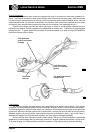
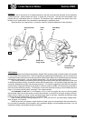
The modular fuel pump/sender assembly uses an electric motor to power a three stage impeller type
pump system submerged within the tank. In order to avoid fuel starvation from surge effects caused by vehicle
acceleration and cornering forces, the pump is housed within a reservoir canister kept filled with fuel irrespec-
tive of the tank fuel level. The pump connects with a port on the bottom of the canister fitted with a strainer
sock in order to screen dirt particles from the fuel line and help separate any water content from the fuel. The
first stage impeller pump draws fuel from the tank via this sock, and outputs it into the canister, which fills up to
its overflow port in the top surface. The second stage impeller pump draws fuel from within the canister via
another strainer sock, and supplies the high pressure third stage tubine pump which outputs fuel from the top
end of the pump into the flexible pipe connected to the supply connection on the pump assembly top plate.
From here, fuel is piped to the fuel rail on the engine, from which it returns to the inlet connection on the top
plate and spills into the canister to supplement the primary pump output and keep the canister fully filled.
An umbrella valve in the bottom of the canister allows fuel to flow into the canister whenever the tank
level is higher than the canister level. This feature also permits a continued fuel supply to the secondary pump
stage in the event of a blocked primary stainer.
For further details of the fuel pump, filter and tank, refer to section LH.
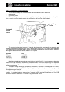
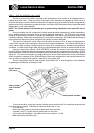
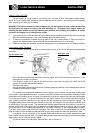
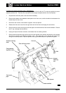
Pre-'boot box' cars
Fuel
pump
fuse
ohs11
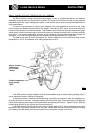
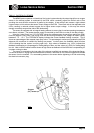
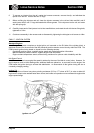
'Boot box' cars
Fuel
pump
fuse
ohs82