


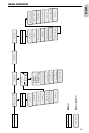

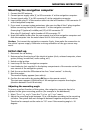
Completing electrical connections, ill. 12
Lay all cables carefully. Refer to the connecting diagram on the fold-out page at the
end of the booklet and to the table below.
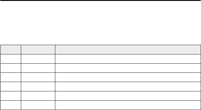
Power supply cable 6 (ISO connector A):
Pin no. Cable color Connection
A1 black/white speedometer signal input
A2 white/yellow back-up lights (reversing signal)
A3 white/brown mute signal output (open collector)
A4 red +12V permanent power supply (via cable fuse 10 A if necessary)
A7 violet +12V switched (must not be interrupted during engine start)
A8 brown negative battery pole
A
Only connect electrical signals to appropriate terminals in the vehicle.
A
In the case of a direct connection to the battery secure the positive connection (red
lead) with a 10 A fuse close to the battery (max. 4 - 6 inches).
1. Connect the free cable ends A4, A7 and A8 of the power supply cable 6 to suitable
terminals in the vehicle according to the connecting diagram and the table.
2. Do not cut off unused cables! Wind them together and tie them back! They may be
used later to install additional features.
Speedometer signal (ISO connector A):
Connect the black/white cable A1 from cable harness to the tapping position of the
speedometer signal.
Note: Many cars are supplied with the speedometer signal on one of the car radio
connectors. Ask your car dealer for more information.
A
Never tap the speedometer signal from the ABS control!
Further signals (ISO connector A):
Connect the white/yellow cable (A2) to a suitable connecting point of the back up
lights (positive pole of the reversing lamp).
Connecting system components (ISO connector B):
Connect the plug of the remote control cable to the socket on the signal cable
harness 5.
Connect the loudspeaker (accessory) with the 3.5 mm jack to the 3.5 mm plug of the
signal cable harness 5.
The loudspeaker impedance should be between 4 and 8 Ohms.
MOUNTING INSTRUCTIONS
48