


8
A single wire should be run from the fuel sender to the control box terminal marked FUEL. If
your wiring harness already has a wire routed through the vehicle for the fuel sender then it may
be used. If using a wire from an existing harness, make sure that the wire does not have power.
The fuel sender gets power from the control box only. Fuel senders get their ground from the
sender mounting plate. Make sure that a ground wire is connected from one of the sender
mounting bolts to the vehicle frame.
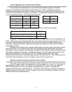
The fuel sender type is selected using the DIP programming switches located inside the
control box. The settings are discussed later in the section on internal adjustments.
If the fuel display shows “—“ this indicates that the control box is sensing a short to
ground or out-of-range error from the sender or sender wire. If the fuel display shows “EE” this
indicates that the control box is sensing an open circuit or out-of-range error from the sender. If
either indication remains on the display, inspect the sender wire for damage, check the routing
of the sender wire, check the sending unit grounding, and check that the DIP programming
switches are set correctly for the sending unit that is connected.
TRIP
The TRIP terminal is used for the trip odometer function, for setting the oil warning set
point (see WRN), and for speedometer calibration (see SPEEDOMETER CALIBRATION). The
TRIP input is activated by a ground connection. The push button switch supplied (or any
normally open switch) is wired by connecting one terminal to TRIP and the other terminal to a
ground. When the trip button is pressed, the odometer display will switch from full odometer
mileage to the trip mileage or from the trip mileage to the full odometer mileage. When the trip
mileage is shown a lower case “t” will be displayed to the left of the trip meter reading. “t 000.0”
Pressing and holding the trip button for 7-8 sec. will enter the demonstration mode.
RESET
The RESET terminal is used for the trip odometer function, for setting the water warning
set point (see WRN), and for the speedometer calibration (see SPEEDOMETER
CALIBRATION). The RESET input is activated by a ground connection. The push button
switch supplied (or any normally open switch) is wired by connecting one terminal to RESET
and the other terminal to a ground. When the reset button is pressed and held for a few
seconds, the trip miles will be reset to zero. This will not affect the full odometer mileage.
Pressing the reset button will also exit the demonstration mode.
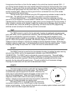
CHECK
The check engine terminal is used with fuel injection ECM’s
to display engine problems and trouble codes. The CHECK input
is activated by a ground signal from the ECM. Whenever the
check input is grounded the system will display a lower case “c” to
the left of the speedometer. When the ECM is placed into
diagnostic mode trouble codes can be read by counting the
flashes. Consult a service manual for the fuel injection system that
you have for further information on trouble codes.
With some ECM’s a 12 volt light bulb may need to be
connected in addition to our CHECK input in order to provide
proper current loading. In this case both the bulb and our display system indicator would both
come on when the check engine wire was set.