


6
SPEED
The vehicle speed sensor (VSS) connects to this to tell the system how fast the vehicle is
moving. For two wire speed sensors, like the one Dakota Digital supplies with this system, the
polarity of the wires does not matter. Connect one wire to ground and the other to the speed
terminal. The speed sensor ground wire should be brought back to the control box to ensure a
proper signal is received. Twisting the ground and signal wires around each other provides an
additional level of interference protection. The speed signal wire should not be routed along
side ignition or other high current or high voltage wires.
For vehicles which already have a vehicle speed signal, tap into the VSS wire and
connect it to the speed terminal. You may have to consult a vehicle service manual or wiring
diagram to determine wire color and location.
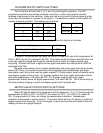
This system can accept 4000 ppm – 128000 ppm speed signals. The sensor that Dakota
Digital provides is an 8000 ppm type. The speedometer is fully adjustable and calibration is
discussed in a later section. Failure to calibrate the speedometer may cause your odometer mileage to
increase very rapidly if the speedometer is reading too fast.
TACH
Depending on the type of system that you have there may be no tachometer, a bar graph
tachometer, a digital tachometer, or both bar graph and digital readouts. Connect the tach
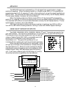
terminal to the ignition system. On vehicles using a separate ignition coil, connect to the
negative side of the coil. The negative side of the coil will be the wire that goes to the points or
electronic ignition module. For GM HEI ignition equipped motors, connect the tach terminal to
the terminal marked “TACH” or on some systems, to a single white wire with a spade terminal
on it. On MSD ignition systems, connect to the TACH output terminal. With magneto system
connect to the kill wire for the tach signal. Do not connect the TACH terminal to the secondary,
or high voltage side, of the ignition coil. To ensure that the ignition system does not interfere
with any other dashboard functions, do not run the tachometer wire along side any other sender
or input wires. DO NOT USE SOLID CORE SPARK PLUG WIRES WITH THIS DASHBOARD
SYSTEM. Solid core ignition wires cause a large amount of electromagnetic and radio
frequency interference which can disrupt the system operation.
The tachometer is compatible with 4, 6, 8, and 10 cylinder gasoline engines. There are
DIP programming switches inside the control box that set the number of cylinders, tach bar
graph full scale range, and tach display type. These settings are discussed later in the section
on internal adjustments. If a diesel engine is being used and the alternator has a tach output,
then Dakota Digital’s DSL-1 interface will convert the alternator signal to operate the
tachometer.
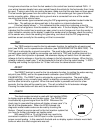
WATER
The water temperature sender included with this system must be used. Other senders
will cause incorrect readings. The sender mounts on the engine block or into the intake
manifold so that the end of the sensor is in the engine coolant flow. The sender gets its
electrical ground connection to the engine block through its threads. Do not use Teflon tape or
thread sealant on the sender threads. Doing so can cause incorrect readings or cause the
gauge to display an out of range indication. A sender with 3/8 NPT thread size is normally
included and 1/8 NPT thread size is available. If the engine you have requires a different thread
size you will need to use an adapter to convert the thread size. Adapters can be found at your
local auto parts dealer or hardware store.