


12
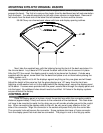
Setting up the control box
SPEEDOMETER CALIBRATION
The speedometer calibration is done using the TRIP and RESET switches. There are
two different ways to calibrate the speedometer. The first method control box uses an auto-cal
mode where you drive one mile (1 km for metric) and the system automatically adjusts the
speedometer calibration. The second method allows you to adjust the speedometer up or down
as you drive.
To enter the auto-calibration mode, begin with the key off. Press and hold both the trip
and reset switches at the same time while the vehicle is being started. The speed will display
“CAL”. Once the switches are released the control box will begin measuring. As you drive the
odometer will display the number of pulses received from the sensor. If the reading stays at
zero as you drive, then check the vehicle speed sensor and speed sensor wiring. Once you
have driven exactly one mile (or km) press and hold both of the switches again. The system will
calculate and store the new speed calibration. Once the switches are released the system will
restart and go back to normal operation.
While the system is in the auto-cal mode the voltage, fuel, oil, and water gauges will
remain blank will not change until the speed calibration is completed.
To enter the speedometer adjust mode, press and hold both the trip and reset switches at
the same time while the system is on and operating. The switches will need to be held for about
4-6 seconds. The odometer will display “AdJUSt” and the other gauges will function normally.
Release the switches. Pressing and holding the TRIP switch will increase the speedometer
reading. Pressing and holding the RESET switch will decrease the speedometer reading.
Pressing and holding both the TRIP and RESET switches at the same time will store the current
speed calibration and exit the speed adjust mode. While the system is in speed adjust mode
the odometer will continue to accumulate normally, even though it is not displayed.
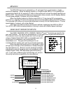
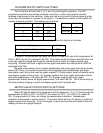
FUEL DIP SWITCH SETTINGS
The control box can read 5 different types of fuel senders. The DIP programming
switches are located inside the control box, so the cover must be carefully removed to get
access to the switches. Make sure the key is turned off before opening up the control box so
that there is no power to the system. The switches labeled 1, 2, and 3 are used to select the
different sender types. Once the switches have been set, replace the cover before turning the
system on. The sender types are listed below, along with their corresponding empty and full
resistance readings. If you do not know what type of sender you have, use an ohmmeter to
measure the fuel sender resistance when it is full and empty.
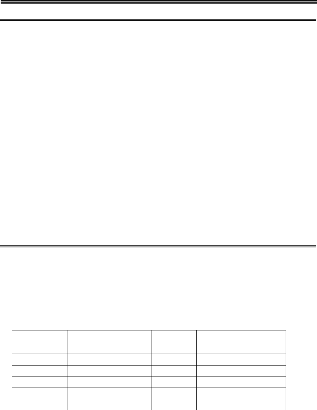
Sender type Empty R Full R Switch #1 Switch #2 Switch #3
GM 0-30 ohm 0 ohms 30 ohms ON ON OFF
GM 0-90 ohm 0 ohms 90 ohms OFF ON OFF
GM 40-250 40 ohms 249 ohms ON ON ON
FORD 73 ohms 10 ohms OFF OFF ON
VDO 10 ohms 180 ohms OFF OFF OFF
SW/SUN 240 ohms 33 ohms OFF ON ON
SW/SUN is the default setting when systems are shipped.