


20
CLOCK
Wiring instructions for VFD systems with a clock built in.
Introduction:
The clock displays the current time in 12 hour format with an AM/PM indicator. The AM/PM indicator
appears as a dot that will be displayed in the upper left corner. The dot will be on every other 12 hour period (on
during AM and off during PM). The high brightness display matches our other Odyssey and STR series gauges
and has the same night brightness dimming capability. Features included are:
• Quartz accuracy.
• Night dimming feature.
• Very low standby power to prevent battery drain.
• High Visibility VFD display for sunlight readability.
Operation:
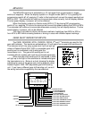
The gauge needs the red, orange, and black wires connected to operate. The red wire should have
switched 12 volt power from an ACC. point on the fuse panel. The orange wire should have constant 12 volt
power. The black wire should be connected to a good ground point. When the blue wire has 12 volts, it will dim the
display for night viewing.
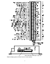
Setting the time:
Using a small, thin object such as a pen or hairpin, press “set” buttons through front lens access holes.
The access holes are on the right side of the lens. Top “set” button advances hours, bottom “set” button advances
minutes.
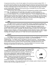
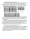
Wiring:
BLACK - connect to a good ground point in the vehicle.
RED - connect to switched 12 volt power point.
(An accessory terminal will work for this.)
ORANGE - connect to a constant 12 volt power point.
(This will keep the correct time.)
BLUE - connect to the tail light circuit.
DAKOTA DIGITAL, INC. * 3421 W. Hovland Ave. * Sioux Falls, SD 57107 * (605) 332-6513
www.dakotadigital.com
dakotasupport@dakotadigital.com