


MAN# 650280:D
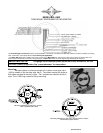
STATUS AND WARNING INDICATORS
The right turn, left turn, and high beam indicators are activated by 12
volts at their respective hook-up wires. The right turn signal wire is green,
the left turn signal wire is orange, and the high beam wire is purple. These
can be connected to the same wires that the indicator lights would be
connected to. The display system wire colors may not match the wire colors
in your electrical wire harness; consult a service manual to determine the
color code and location of any wires you cannot locate.
The neutral, low oil, and check engine indicators are activated by
ground at their respective hook-up wires. The check engine wire is pink, the
low oil wire is brown, and the neutral wire is white/green.
LOW VOLTAGE WARNING
When the voltage drops below the warning limit with the engine running, LO and your current voltage will be
displayed. (default warning limit is 11.0V)
SECURITY SYSTEM INDICATOR
The security system indicator is a red light that is activated by 12 volts to the purple wire. It will light up
whether the gauge is powered or not.
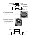
SPEEDOMETER
Failure to calibrate the speedometer may cause your odometer mileage to increase very rapidly.
The speed input connector plugs into the speed sensor to tell how fast you are traveling. On cable driven
applications, the external sensor connects to the speedometer cable and provides the electric signal. The sensor is
normally bolted directly to the bottom of the speedometer, but can also be remote mounted. The sensor has a 5/8”
course thread fitting that accepts mid-80’s and earlier cables directly. For newer cycles, the speedometer cable will
need to be replaced with one having the correct fitting.
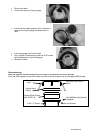
With transmissions having the built-in electric sensor, a three-wire harness adapter connects the
transmission speed sensor to the speedometer. This system will also accept most aftermarket inductive, Hall-
effect, or ground switch sensors.
For three wire Hall-effect sensors, refer to the installation instructions for the sensor to determine wire color
code. Most three wire sensors use the following color code: RED – power, BLACK – ground, WHITE – speed
signal. Connect the sensor signal wire to the MCL-2002 main harness gray wire, connect the sensor power wire to
the white/purple wire, and connect the sensor ground wire to the white/black wire.
For a speed sensor integrated into a vehicle wiring harness, consult a service manual to determine the color
code and location of the speedometer signal. If the factory harness supplies +5V to the sensor, please utilize
the factory connection in place of the white/purple power wire.
The speedometer is fully adjustable and calibration is discussed in the Speedometer Setup section.
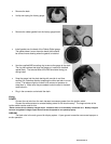
TACHOMETER
The tachometer is used by connecting the yellow wire from the main harness to the negative side of the coil
or to an ignition module tach output. The tachometer is adjustable for 1 - 15 cylinder settings. The one cylinder
setting is used for single-fire ignition systems without a buffered tach output.
If there is not a pink wire attached to the stock gauge harness: for carbureted models connect to the pink
wire at the coil and set the tach for 2 cylinder; for fuel injected models connect to either the blue/orange or
yellow/blue under the seat in the harness along the right side frame rail and set the tach for a 1 cylinder. For tach
signals integrated into a vehicle wiring harness, consult a service manual to determine the color code and location
of the tachometer signal. The bar displays rpm x 1000 with a range of 350 – 7000 rpm.
CLOCK
The clock uses a 12 hour format and can be set by pressing and holding the switch while the clock is
displayed. After the switch is held for a few seconds the hours will begin flashing. Momentarily pressing the switch
will change the hours, holding the switch will move to the minute set and the minutes will begin flashing.
Momentarily pressing the switch will now change the minutes. Holding the switch will exit the clock set mode.
E
A
B
MPH
km/h
N
RPM
0
1
2
3
4
5
6
7
V
P