


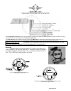
MAN# 650280:D
Troubleshooting guide
Problem Possible cause Solution
Gauge will not light up. Red wire does not have power. Connect to a location that has power.
Black wire is not getting a good ground. Connect ground to a different location.
Gauge is damaged. Return gauge for repair. (see instructions)
Clock shows “ : “ only. White/red wire does not have power. Connect to a location that has constant power.
Clock resets when key is off. White/red wire does not have constant power. Connect to a location that has constant power.
Gauge lights up, but speed VSS wire is not connected properly. Check connection from VSS wire to speed signal wire.
will only show zero. Speed sensor not grounded properly. Move ground to different location, preferable close to the
speedometer ground.
Speed sensor is not being turned by Check cable connection between sensor and transmission.
transmission. Sensor can be tested by spinning the cable with a drill.
Sensor is not sending a speed signal. Check for a damaged or malfunctioning speed sensor.
Gauge is not calibrated. Gauge must be recalibrated (see instructions).
PLEASE – SET – SPEED Speedometer not calibrated. Gauge must be calibrated to your vehicle (see instructions)
Speed reading is erratic or Speed sensor wire is loose or broken. Check all wire connections and inspect wire for breaks.
jumps around. Cable is loose or broken. Check cable between sensor and transmission.
Poor ground connection. Check ground connection on speedometer and sensor.
Ignition Interference. Check for tachometer wires routed with VSS signal wires.
Check for VSS signal wires routed near ignition coils.
Check for poor ignition system ground.
Use suppression spark plug wires.
Speed reading is incorrect. Gauge is not calibrated correctly. Gauge must be calibrated (see instructions).
Gauge lights up, but tach Yellow wire is not connected properly. Check connection from yellow wire to tach signal wire.
will only show zero. Ignition system not grounded properly. Check engine and ignition system grounds.
Gauge is not grounded properly. Check gauge and engine grounds.
Tach signal type is not set correctly. Change the tach signal type (see instructions).
Gauge is not calibrated. Gauge must be recalibrated (see instructions).
Tach reading is erratic or Tach signal wire is loose or broken. Check all wire connections and inspect wire for breaks.
jumps around. Poor ground connection. Check ground connection on tachometer, engine, and ignition
system.
Update rate is too fast. Reset display update speed slower.
Tach reading is incorrect. Gauge is not calibrated correctly. Gauge must be calibrated (see instructions).
Gauge will not dim. Auto dimming is disabled. Check setting under “night” menu.
Gauge remains dim at all Light sensor is covered. Make sure the bottom center of the gauge lens is clean and
times. not obstructed.
High beam, Left turn, Right Loose or incorrect connection to indicator wire. Check that the appropriate indicator wire has about 0 volts
turn or Security indicator when the indicator should be off and about 12 volts when
does not work. the indicator should be on.
Neutral, low oil, or engine Loose or incorrect connection to indicator wire. Check that the appropriate indicator wire has about 12 volts
indicator does not work. when the indicator should be off and about 0 volts when the
indicator should be on.
Turn signals do not cancel Output speed signal to stock cancel is loose Check the connections on the solid.
automatically. or not connected properly. white wire coming from the gauge.
Speedometer is not calibrated. Calibrate the speedometer.
Speed sensor is not working. If the speedometer always shows zero, check speed sensor
voltages.
Turn signal cancel module is not working. Test turn signal module according to the bike’s service manual.
Pressure reading does not Pressure sender is not connected. Sender must be connected before the reading will be
displayed.
show up. Sender wire is loose or broken. Check all wire connections and inspect wire for breaks.
Sender is not grounded. The sender grounds through its mounting threads. Make sure
the threads are clean and tight.
Temperature reading does Temperature sender is not connected. Sender must be connected before the reading will be
displayed.
not show up. Sender wire is loose or broken. Check all wire connections and inspect wire for breaks.
Sender is not grounded (SEN-1043). The sender grounds through its mounting threads. Make sure
the threads are clean and tight.
Pressure or temperature Sender is shorted to ground. Inspect wire for bare insulation or pinching.
reading shows “- -“ .
Speed sensor voltage checks. All checks should be made with the sensor connected to the gauge and the key
on. Checks should be done with a volt meter and not a test light.
3-wire sensor: Red wire should have 9-11 volts dc, slightly less than battery voltage.
Black wire should show ground, 0 volts dc at all times.
White wire should vary between 0 and 5 volts dc as the gear teeth pass by the sensor.
2-wire sensor: Measure the voltage between the two sensor wires. With the wheel spinning the voltage should be
about 1-10 volts ac (make sure the meter is set to AC volts and not DC volts for this check).