


INSTALLATION CAUTIONS & WARNINGS
**FOR SAFETY REASONS, DO NOT INSTALL in vehicles with MANUAL TRANSMISSIONS.** If accidentally left in
gear, a remote started vehicle could become a self-propelled threat to life and property.
DO NOT extend the Remote start ignition harness length. Mount the module so that main harness reaches all ignition
switch wiring. Extending these wires could result in poor or improper performance.
DO NOT route any wiring that may become entangled with brake, gas pedals, steering column or any other moving parts
in the vehicle.
DO NOT exceed the rated output current of any circuit on the Remote start module. Failure to observe this warning will
result in damage to the unit that is not covered under warranty.
DO NOT remote start the vehicle in a closed garage! Make sure that the garage door is open or there is adequate
ventilation. Failure to observe this rule could result in injury or death from poisonous Carbon Monoxide fumes.
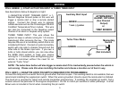
WIRING
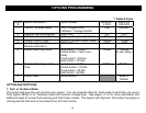
PIN 9: BLACK: MAIN SYSTEM GROUND
Connect to chassis metal of the vehicle. An existing bolt or screw may provide an adequate ground, or drill a small hole,
scrape away paint and attach using a sheet metal screw & star washer. This wire must be connected to a proper ground
or undesirable and inconsistent operation will occur. Do not use Factory ground locations.
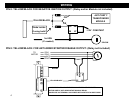
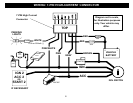
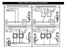
PIN 8: YELLOW/BLACK: (-) IGNITION OUTPUT / ANTI GRIND RELAY
Use this wire to turn on Anti-theft /Transponder Bypass modules, an Anti grind output, or to trigger a 3
rd
Ignition relay if
your particular installation requires a 3
rd
Positive Ignition circuit. This wire turns on when the remote start button is
pressed and stays on through the duration of the remote start. When using this wire for an Anti grind output, an optional
Relay is needed to interrupt the Starter circuit preventing accidental grinding of the starter if key is turned too far after a
remote start. External relays for Ignition #3 or Anti Grind are not included. See diagrams on NEXT PAGE.
PIN 7: BROWN: (-) AUX OUTPUT (TRUNK POP)
This output will provide a ground pulse when button #3 (Trunk) on the remote transmitter is pushed to activate a factory
electric trunk release or other optional accessory.
3