


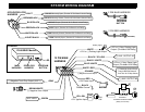

COMPONENT MOUNTING
CONTROL MODULE: Locate the module underdash as high as possible. Driver’s Side usually provides an
easy location for the majority of the wiring connections. The antenna wire should be routed away from any
metal if possible. DO NOT alter the length of the antenna wire, or ground the antenna wire.
OVERRIDE / PROGRAM BUTTON: Mount the button in a hidden but accessible location. It is used for
emergency-disarm (when optional starter disable is installed) without the use of the transmitter and for
programming features of this unit.
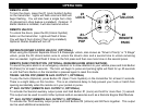
LED: The optional Red LED provides a useful theft deterrent. The LED blinks after you lock the vehicle with
your remote simulating an alarm system. The LED is also required when programming options. Choose a
visible location in the dash or console for the LED’s location.
WIRING
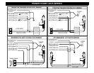
WHITE WIRE: +12V or (-) NEGATIVE PARKING LIGHT (Jumper Selectable On-Board Relay 10A)
Connect to switched +12V parking light wire at back of light switch. If this is not possible, connect directly to
one of the parking lights at the front of the vehicle. If your vehicle requires a (-) Negative Ground signal to
activate the parking lights, then you have to open the control and move the jumper located on the circuit board
inside the unit. For European vehicles with separate right and left circuits, use a dual relay or 2 diodes to
separate the output signal. The DEFAULT output is POSITIVE. SEE PAGE 7
BLACK/YELLOW WIRE: (-) AUXILIARY REMOTE OUTPUT 3 (Optional, requires relay)
This wire provides a Negative output for activation of optional or auxiliary devices. It is controlled by Pressing
and Holding Buttons (2) Unlock and (4) Panic together.
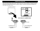
BLACK/WHITE WIRE: (-) NEG. or +12V DOME LIGHT (Jumper Selectable On-Board Relay-10A)
Connect to dome light activation circuit for Negative type circuits. For Positive type circuits, open the control
module and move the jumper the plug as shown in illustration. The DEFAULT is NEGATIVE. SEE PAGE 7.
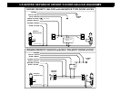
BLUE/WHITE WIRE: (-) PASSENGER(S) DOOR UNLOCK OUTPUT (Optional, requires relay)
Connects to unlock circuit for passenger door(s) when using separate driver’s door unlock option. See DOOR
LOCK WIRING for configuration options.
WHITE/RED WIRE: (-) AUXILIARY REMOTE OUTPUT 2 (Optional, requires relay)
This wire provides a Negative output for activation of optional or auxiliary devices. It is controlled by Pressing
and Holding Button (1) Lock.