


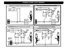
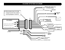

IMMOBILIZER CIRCUIT #1
#1
#2
RED PLUG: LED
BLUE PLUG: VALET
CS-8050
LED
#3
VALET/
PROGRAM
SWITCH
+
BATTERY
(-) NEGATIVE
ARMED OUTPUT
IGNITION
-
#4
#5
#6
+12V
GROUND
#7
(-) NEG. DOME
OR OEM
DISARM
(-) NEGATIVE
HORN OUTPUT
#8
#9
#10
IMMOBILIZER
CIRCUIT #2
(On Board Relay)
(On Board Relay)
WHITE PLUG: DOOR LOCKS
BLUE
RED
WHITE
GREEN
(-) LOCK OUTPUT
BLUE
(-) UNLOCK OUTPUT
RED
+12V FOR RELAYS
MAY REQUIRE RELAY
ANTENNA
*
*
Some systems may not include
a large connector here, however
the wiring diagram is identical.
CS-8050 SYSTEM DIAGRAM