


INSTALLATION PRECAUTIONS & WARNINGS
BEFORE BEGINNING, check all vehicle manufacturer cautions and warnings regarding electrical service (AIR
BAGS, ABS BRAKES, AND BATTERY).
DO NOT ROUTE ANY WIRING THAT MAY BECOME ENTANGLED with brake, and gas pedals, steering
column, or any other moving parts in the vehicle.
COMPONENT MOUNTING
Control Unit: DO NOT mount or wiring harness where they can become entangled with moving parts such as
brake/gas/clutch pedals, or the steering column! The alarm control module should be mounted in a concealed
location. Do not mount the control unit in the engine compartment. The antenna wire should be routed away
from any metal if possible. Do not alter the length of the antenna wire or ground the antenna wire.
LED: Mount in a visible location on the dashboard or console.
Valet/Program Button: Mount button in a hidden but accessible location. It is REQUIRED for emergency
disarm, programming, and valet mode.
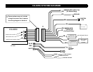
WIRING
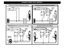
Note: This unit includes High-Security wiring with the critical connection wires being the same BLACK
color to deter or confuse someone from tampering with this unit. Please match the appropriate wire
number with the number on the diagram for proper connection. DIAGRAM : PAGE 8
WIRE #1: Immobilizer Circuit #2 Output:
This is part of the immobilizer circuit (on-board relay). Cut the Starter wire and connect ONE end to this wire.
WIRE #2: Immobilizer #2 Input:
This is part of the immobilizer circuit (on-board relay). Connect the other end of the Starter wire to this wire.
WIRE #3: Chassis Ground:
This wire must be connected to chassis metal of vehicle. Use a sheet metal screw and star washer to insure a
good connection. Keep the ground wire short and try not to use factory ground locations.
WIRE #4: Ignition Switched "ON" and "START" +12Volts:
Connect to an Ignition Wire (or fuse in the fuse box) that shows +12 Volts Power when the key is in "ON" and
"START" (cranking) position.