


128-6996A
7 of 28
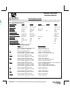
WIRING CONNECTIONS: Multi Pin Accessory Input/Output Harness
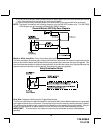
White w/ Red Trace Wire: Parking Light Flasher Feed
This wire is the common contact of the on board parking light flasher relay. If the vehicle you are working
on has +12 volt switched parking lights, connect this wire to a fused + 12 volt source. (Max. 15 Amps)
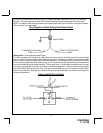
NOTE: If the vehicle's parking lights are ground switched, connect this wire to chassis ground.
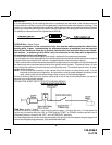
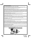
White Wire: Parking Light Flasher Output
This wire is the normally open contact of the on board parking light flasher relay. Connect this wire to the
vehicle parking light feed wire. See diagram below for details on wiring positive switched parking light
circuits.
7
PINK/WHITE Wire: Ignition 2 Output
Connect this wire to the ignition 2 wire from the ignition switch. This wire will show + 12 volts when the
ignition key is turned to the "ON" or "RUN" position and is some cases the "START" or CRANK" position.
This wire will show 0 volts when the key is turned to the "OFF" and "ACCESSORY" positions.
NOTE: See programming information concerning this wire.
ORANGE Wire: Accessory Output
Connect this wire to the Accessory wire from the ignition switch. This wire will show + 12 volts when the
ignition switch is turned to the "ACCESSORY" or "ON" and "RUN" positions and will show 0 volts when
the key is turned to the "OFF" and "START" or "CRANK" positions.