


128-6996A
10 of 28
10
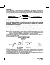
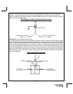
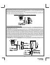
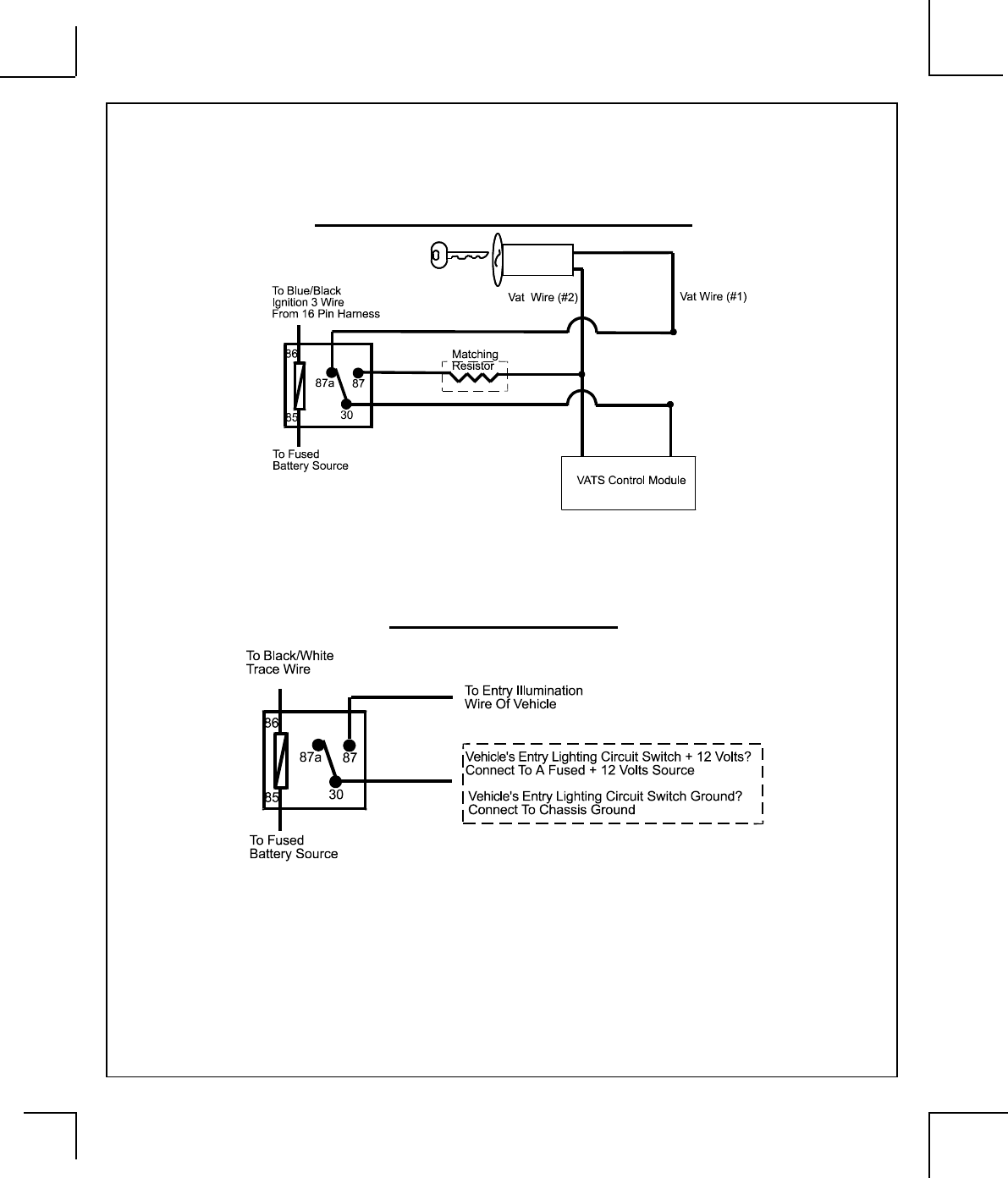
Black w/ White trace Wire: Entry Illumination Ground Output
This wire provides a 30 second ground output (300 mA Max.) whenever the remote is used to disarm the
alarm or to unlock the doors and provides a continuous pulsed output whenever the alarm is triggered. This
wire should be connected to an external relay and wired to the vehicles interior entry lighting whenever the
optional Interior Illumination circuit is desired. See below for relay wiring details.
Entry Illumination Detail
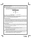
Grey Wire: Negative Inhibit Input plus Trigger When Armed
The Grey wire provides an instant shutdown for the Remote Start Control Module whenever it is grounded
and trigger whenever the unit is armed. Connect the Grey wire to the hood pin switch previously installed.
This wire must be routed through a grommet in the firewall and connected to the hood pin switch. If the pin
switch is to be used with an alarm system, connect this wire using the diode assembly provided.
IMPORTANT! This connection is a safety wire and must be connected as shown and tested as
specified.
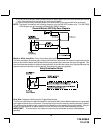
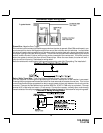
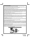
4. Cut (#1) wire (as shown), and connect the ignition switch side of the cut wire to terminal #87a of the
relay. Connect the other side of the (#1) wire to terminal #30.
5. Connect the previously selected resistor from terminal #87 to the second (#2) wire (as shown).
NOTE: The above information and following diagram is for the GM VATS system only. For GM PASS
LOCK System you will require the Audiovox AS-PASS II Module.
General Motors VATS By-Pass Diagram