


128-6996A
5 of 28
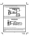
CONTROL SWITCH:
Select a mounting location known and accessible to the operator of the vehicle. A lower dash panel, kick
panel, or glove box is desirable. Inspect behind the chosen location to insure that adequate clearance is
allowed for the body of the switch, and also that the drill will not penetrate any existing factory wiring or
fluid lines. Drill a 1/4" hole in the desired location and mount the switch by passing it through the panel
from the underside. Secure the switch using the nut, star washer, and on/off face plate. It is suggested
that the switch be oriented to allow the on position to be up toward the driver and the off position to be
down or away from the driver. Route the switch's connector toward the control module.
SHOCK SENSOR:
Select a centrally located, solid mounting surface for the shock sensor that will allow consistent opera-
tion from all areas of the vehicle. The selected location must be within 18" of the control module to allow
routing and connecting of the 4 pin harness. Secure the shock sensor to the chosen location using two
#8 self tapping sheet metal screws. The sensor can also be secured to an existing dash brace using
cable tie straps. Whichever mounting method is used be sure to allow access to the sensitivity adjust-
ment potentiometer for use later in the installation.
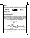
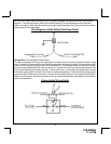
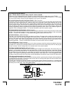
STARTER INHIBIT RELAY:
Select a mounting location within 12" of the ignition switch's low current start solenoid wire. Secure the
relay to an existing harness in the chosen location using a cable tie around the relay's wiring harness.
CAUTION! Do not wire tie the metal bracket to an existing wiring harness as vibration may cause chaffing
and shorting damaging the factory wiring. If an existing harness is not available then secure the relay's
metal mounting tab to an under dash metal brace with a #8 self tapping sheet metal screw. Wire the relay
as per the diagram found later in this manual.
The AX-900 is to be used in vehicles with AUTOMATIC TRANSMISSIONS only! Although this combina-
tion Alarm/Remote Start unit is a sophisticated system with many advanced features, IT MUST NOT be
installed into a vehicle with a manually operated transmission. Doing so may result in serious per-
sonal injury and property damage.
IMPORTANT!
DO NOT PLUG THE SIX PIN MAIN POWER HARNESS OR THE MULTI PIN INPUT / OUTPUT HARNESS
INTO THE CONTROL MODULE UNTIL ALL CONNECTIONS TO THE VEHICLE HAVE BEEN MADE.
AFTER SELECTING YOUR TARGET WIRES AS DEFINED BELOW, DISCONNECT THE NEGATIVE
BATTERY CABLE FROM THE VEHICLE BATTERY PRIOR TO MAKING ANY CONNECTIONS.
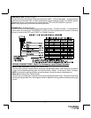
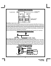
WIRING THE 6 PIN MAIN POWER HARNESS:
RED w/ PURPLE Trace Wire: + 12 volts Battery 1 Source
Connect this wire to a + 12 VDC constant source found at the vehicle's ignition switch using the 30 Amp
fuse and holder provided. This wire provides power for the control circuit as well as the ignition 1 and
ignition 2 relays.
RED Wire: + 12 Volts Battery 2 Source
Connect this wire to a + 12 VDC constant source found at the vehicle's ignition switch using the 30 Amp
fuse and holder provided, but NOT the same vehicle wire as used by the battery 1 source. Most vehicles
have more than one battery source supplying power to the ignition switch. Separate feed wires must be
used for the Red and Red/White wires. If your vehicle does not have two battery feed wires at the ignition
switch then it is possible to connect both wires to the vehicle's battery. This wire provides power for the
start relay and the accessory relay.
5