


128-6996A
16 of 28
16
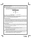
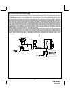
4 Pin Upgrade Telematic Module:
Red = + 5 Volts / Black = Ground / White = Data TX / Yellow = Data RX
Connect the 4 pin harness found in the Telematic one way module kit to the mating port on the PTUGM.
NOTE: If using the TWO WAY Telematic module, only Ground, TX, and RX are used on this port, the + 12 volt supply
for the two way module must be sourced separately or the unit will not operate.
2 Pin Valet/Program/Override Push-Button Switch: (Blue Connector)
The Black & Grey twin lead wires loaded in the two pin blue connector are the ground supply and program/valet/
override input of the Remote Start unit. When the Grey wire is grounded, under certain conditions, the unit will
enter the valet mode. When the Grey wire is sequentially grounded under other conditions, the unit will enter the
various program modes. Route the twin lead Black and Grey wires from the Valet/Program switch to the remote
start unit and plug the two pin connector into the mating blue connector shell of the control module. Refer to the
remote programming, feature programming and function programming shown later in this installation guide for
operation of the valet/program switch. For override information, refer to the owners manual.
4 Pin Antenna/Receiver Connector: (White Connector)
Plug the previously routed connector from the antenna receiver assemble into the mating connector of the control
module. This connector supplies 12 volts, ground and RF data from the antenna receiver to the remote start
module. Be certain this connector is firmly seated making good contact to the control unit.
4 Pin Shock Sensor: (White Connector)
The Red (+12 volt), Black (ground), Blue (pre-detect) and Green (full trigger when armed) wires loaded into the
white connector shell are the inputs/outputs of the shock sensor. Route the 4 wire harness from the shock
sensor to the remote start control unit and plug the 4 pin white connector into the mating 4 pin connector shell of
the control module. Note: While operating under the control of the remote start unit the shock sensor will be
shunted (bypassed). Once the remote start shuts down, the shock sensor will be re-enabled.
2 Pin LED Harness: (White Connector)
The Red & Blue wires loaded into the two pin mini white connector control the anode and cathode of the dash
mounted LED. Route the twin lead Red and Blue wires from the LED to the remote start control unit and plug the
two pin connector into the mating white mini connector shell of the control module.
3 Pin Door Lock/Unlock Harness: (White Connector)
The Green and Blue wires will provide either a pulsed ground output to the factory door lock control relay, or a
pulsed + 12 volt output to the factory door lock control relay. In either case, the maximum current draw through
these outputs must not exceed 300 mA. The Blue/Red wire will provide a pulsed ground only, and will only provide
an output when the unlock button of the transmitter is pressed a second time after a first unlock command was
issued. This is used for second step unlock or all doors unlock in a two step circuit. In this arrangement, Green
is used to control the drivers door unlock relay, and the Blue/Red will be used to control unlock of all other doors.
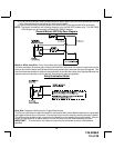
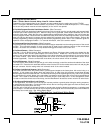
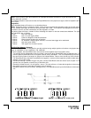
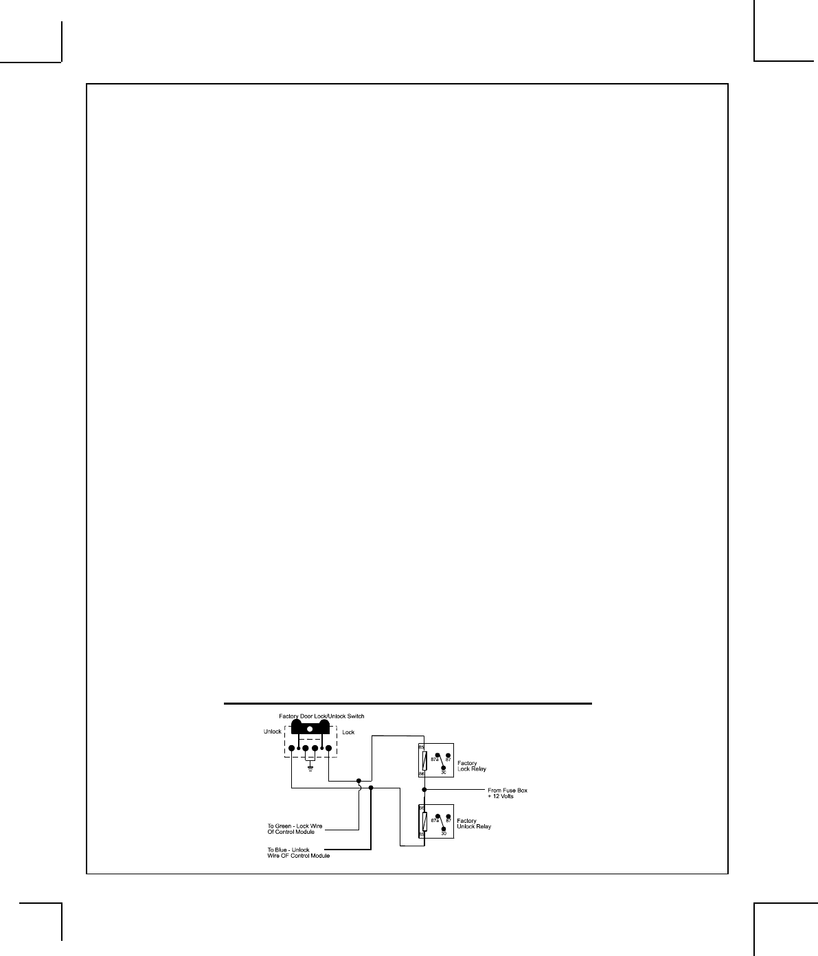
3 Wire Ground Switched Door Lock Circuits:
In this application, the Green wire of the two pin harness provides a ground pulse during the arming sequence,
or pulsed ground lock output. Connect the Green wire to the low current ground signal wire from the factory door
lock switch to the factory door lock relay.
The Blue wire of the two pin harness provides a ground pulse during the disarming sequence, or pulsed ground
unlock output. Connect the Blue wire to the low current ground signal wire from the factory door unlock switch to
the factory door unlock relay. See Wiring Details Below.
3 Wire Ground Switched Door Lock/Unlock Wiring Detail