


128-6996A
26 of 28
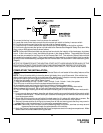
5. Check the vehicle's wipers, lights, horn, etc.... to insure proper operation.
6. Replace all panels that were removed during installation, and retest the system.
7. Explain all activated features and safety systems associated with Remote Start Unit installed to the
customer.
8. Place the Valet Switch Tag and or the Remote Start Control Switch Tag on their respective switches and
point these out to the customer.
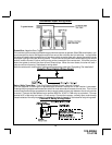
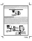
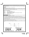
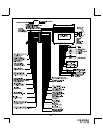
24 Pin Main Harness
White Parking Light Output
White/Red Parking Light Polarity Input
Green/Orange (-) Headlight Control Output 300mA
Orange (-) Starter Disable Ground When Armed Output 300mA
Brown/Black (-) Horn Honk Output 300mA
Vacant Not Used
Black/White (-) Domelight Supervision Output
Blue/Black (-) 3rd Ignition Output (-) During Remote Start 300mA max
Light Blue/Black (-) Channel 7 Output Pulsed 300mA
White/Black (-) Channel 6 Output Pulsed 300mA
Purple/Black (-) Channel 5 Output Pulsed or Latched 300mA
White/Blue (-) Channel 4 Output Pulsed or Latched 300mA
Grey/Black (+) 12 V Diesel Wait To Start Input
Red/White (-) Trunk Pop Output Pulsed 300mA
Black (-) Chassis Ground Input
Brown (+) Siren Output
Purple/White Tachometer Input
Blue/White (-)Instant Trigger Input
Blue (-) Trunk Pin / Instant Trigger Input (Shunt During Trunk Pop)
Green (-) Door Trigger Input
Brown/Red (+) Brake Pedal Shutdown Input
Purple (+) Door Trigger Input
White/Green (-) Remote Start Activation Input
Grey (-) Hood Pin Shutdown and Trigger Input
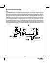
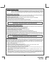
6 Pin Heavy Gauge Remote Start Harness
Orange (+) 12 V Accessory
Pink (+) 12 V Ignition Output
Red (+) 12 V Constant Input
Red/Purple (+) 12 V Constant Input
Purple (+) 12 V Starter Output
Pink/White (+) 12 V 2nd Ignition Output
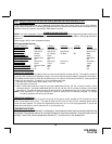
4 Pin Auxiliary Output Harness
Light Green/Black (-) Factory Alarm Disarm Output (Pulse Before Start) 300mA
Light Blue (-) Pulse After Crank 300mA
Black/Red (-) Factory Alarm Re-Arm Output (Pulse After Shutdown) 300mA
Black/Yellow (-) Second Starter Output (Pulse During Crank) 300mA
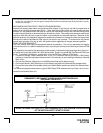
4 Pin Shock Sensor 4 Pin Telematic Port Harness
Red (+) 12 Volt Constant White Data Tx
Black (-) Ground When Armed Output Yellow Data Rx
Green (-) Full Alarm Trigger Input Black Ground
Blue (-) Warn Away Trigger Input Red (+) 5 V
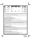
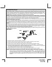
3 Pin Door Lock Harness 2 Pin Transponder Bypass Harness
Green (+) Unlock / (-) Lock 300mA max Red(+) 12 V Constant 300mA
Blue (+) Lock / (-) Unlock 300mA max Black(-) Gnd Out Per R/S Feature # 10 Setting 300mA max
Blue/Red (-) 2nd Unlock 300mA max
26