


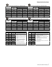


A-FRAME ASSEMBLY
9
64060 (2005-810&8611SkidSteer).doc
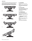
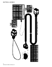
1. The manifold and angle cylinders have been secured to the
A-Frame at the factory; however, each contains several
components that you will need to install.
2. Remove the A-Frame cover to gain access to the manifold.
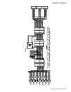
3. Each of the hose ports on the manifold are covered with
stretch wrap. Remove the wrap and install adapter (60272)
to ports #1, 2, 7, 8, 9 & 10.
NOTE: DO NOT let any foreign objects enter into the open ports.
The valves can become contaminated and greatly hinder the
plow’s performance. Torque to proper specifications.
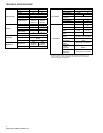
NOTE: All ports are identified by a stamped number on the
manifold. The numbers also identify the hydraulic functions,
which can be referenced on the label under the manifold cover.
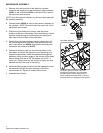
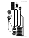
4. Route the hydraulic hose groupings from the pivot beam to
the access holes located on the sides of the a-frame.
Connect the hoses to their respective adapters on the
manifold.
CAUTION: When handling the manifold, hold the
manifold at the sides of the block. Never handle the
manifold by coils. Doing so can cause a solenoid
cartridge to bend, causing the cartridge to stick when
activated.
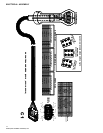
5. Remove the dust cap from both of the hydraulic angle
cylinder ports and attach a 90° adjustable elbow adapter
(60005) to each port. Each adapter should be angled toward
the top of the moldboard. Connect one 3/8" x 26" (60223 or
60224 36" for 8611) hydraulic hose to each angle cylinder
adapter. Be careful not to over tighten the hose
connections. NOTE: The cylinder ports should be facing
away from the A-frame. NOTE: The 810SS & 8611SS A-
frame are the same but use different mounting points for the
angle cylinders due to different stroke length on the
cylinders. Use caution when replacing.
6. Connect the hoses to their respective adapters on the
manifold.
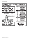
7. Install adapters (60089) to ports “P” & “T” on the manifold.
Connect hydraulic hose (60086) to adapters. Be careful not
to over tighten the hose connections.
8. Install the wire harness.
Ports #1, 2, 7, 8, 9 &10.
Ports “T” & “P”.
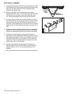
Angle Cylinder Mounting
CV2
8
7
9
10
CV4 PC
2
1
S9 S1 S5
CV5
PT
8611SS USES
OUTER HOLES
810SS USES
INNER HOLES