


TORQUE SPECIFICATIONS
7
64060 (2005-810&8611SkidSteer).doc
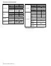
Grade Identification Marking for J429-Grade 5 Bolt Grade Identification Marking for J429-Grade 8 Bolt
SAE J429 – Grade 5 SAE J429 – Grade 8
Tightening Torque Tightening Torque
Nominal
Thread Size
Clamp Loads
(lbs)
“Lubricated” “Dry”
Nominal
Thread Size
Clamp Loads
(lbs)
“Lubricated” “Dry”
1/4-20 2,000 6 ft-lbs 8 ft-lbs 1/4-20 2,850 9 ft-lbs 12 ft-lbs
5/16-18 3,350 13 ft-lbs 18 ft-lbs 5/16-18 4,700 18 ft-lbs 25 ft-lbs
3/8-16 4,950 23 ft-lbs 31 ft-lbs 3/8-16 6,950 32 ft-lbs 44 ft-lbs
7/16-14 6,800 37 ft-lbs 50 ft-lbs 7/16-14 9,600 53 ft-lbs 70 ft-lbs
1/2-13 9,050 57 ft-lbs 75 ft-lbs 1/2-13 12,800 80 ft-lbs 107 ft-lbs
9/16-12 11,600 82 ft-lbs 109 ft-lbs 9/16-12 16,400 115 ft-lbs 154 ft-lbs
5/8-11 14,500 113 ft-lbs 151 ft-lbs 5/8-11 20,300 159 ft-lbs 211 ft-lbs
3/4-10 21,300 200 ft-lbs 266 ft-lbs 3/4-10 30,100 282 ft-lbs 376 ft-lbs
7/8-9 29,435 321 ft-lbs 430 ft-lbs 7/8-9 41,550 454 ft-lbs 606 ft-lbs
1-8 38,600 482 ft-lbs 640 ft-lbs 1-8 54,540 680 ft-lbs 900 ft-lbs
Grade Identification Marking for Metric-Grade 8.8 Bolt Grade Identification Marking for Metric-Grade 10.9 Bolt
Metric Class 8.8 Metric Class 10.9
Tightening Torque Tightening Torque
Diameter
(mm)
Clamp Loads
(Pounds)
“Lubricated” “Dry”
Diameter
(mm)
Clamp Loads
(Pounds)
“Lubricated” “Dry”
5 1,389 3 ft-lbs 5 ft-lbs 5 1,987 5 ft-lbs 7 ft-lbs
6 1,965 6 ft-lbs 8 ft-lbs 6 2,812 8 ft-lbs 11 ft-lbs
7 2,826 10 ft-lbs 13 ft-lbs 7 4,044 14 ft-lbs 19 ft-lbs
8 3,579 14 ft-lbs 19 ft-lbs 8 5,121 20 ft-lbs 27 ft-lbs
10 5,672 28 ft-lbs 37 ft-lbs 10 8,116 40 ft-lbs 53 ft-lbs
12 8,243 49 ft-lbs 65 ft-lbs 12 11,796 70 ft-lbs 92 ft-lbs
14 11,246 77 ft-lbs 103 ft-lbs 14 16,092 111 ft-lbs 148 ft-lbs
16 15,882 125 ft-lbs 167 ft-lbs 16 21,970 173 ft-lbs 231 ft-lbs
18 19,423 172 ft-lbs 229 ft-lbs 18 26,868 238 ft-lbs 317 ft-lbs
20 24,784 244 ft-lbs 325 ft-lbs 20 34,284 338 ft-lbs 450 ft-lbs
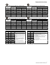
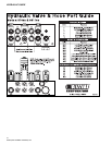
37° JIC Flare Torque Values
Turns Size
Ft-lbs
min.max
Assembly steps
N/A -02 6-7
N/A -03 8-9
2 -04 11-12
2 -05 14-15
1-1/2 -06 18-20
1-1/2 -08 36-39
1-1/2 -10 57-63
1-1/4 -12 79-88
1 -14 94-103
1 -16 108-113
1 -20 127-133
1 -24 158-167
1 -32 245-258
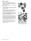
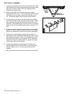
1. Make sure the tubing and threads are
clean.
2. Lubricate the threads with 10W hydraulic
oil.
3. Hand tighten the nut/sleeve to approx. 30
in-lbs.
4. Make alignment marks on the nut and
fitting.
5. Tighten to turn or torque specification.
6. When fully tightened, make a 2
nd
set of
alignment marks at the fully tighten
positioned.
NOTE: Torque values specified are for
threads lubricated with 10W hydraulic oil.
Over tightening will reduce the clamping force
resulting in loss of seal and reduction of flow.
O-Ring Boss Torque Values
Size
Ft-lbs
min.max
Assembly steps
-02 6-7
-03 8-10
-04 13-15
-05 17-21
-06 22-25
-08 40-43
-10 43-57
-12 68-75
-14 90-99
-16 112-123
-20 146-200
-24 154-215
-32 218-290
1. Verify the port, o-ring, sealing surfaces and threads
are clean and free of damage.
2. Lubricate the threads and the o-ring with 10W
hydraulic oil.
3. For an adjustable O.R.B., completely back off the lock
nut and washer.
4. Hand tighten the fitting until it contacts the port
spotface. Point the elbow or tee in the desired
direction and hold.
5. Torque to specification.
NOTE: Torque values specified are for threads lubricated
with 10W hydraulic oil.