


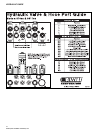

MOLDBOARD ASSEMBLY
8
64060 (2005-810&8611SkidSteer).doc
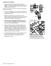
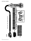
1. Remove dust cap from both of the slide box cylinders
located at the center/rear of the moldboard. Attach adapters
(60007 on the 810SS and 60272 on the 8611SS) to each of
the base ports and rod ports.
NOTE: All of the hydraulic adapters can be found packaged with
the manifold assembly.
2. Connect hoses (60224) to each of the hydraulic adapters on
the cylinders. NOTE: Review the label on each hose for the
appropriate part number
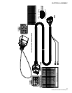
3. Position the pivot beam and A-frame, near the mount
locations at the rear of the blade. Place the slide box cylinder
hydraulic hoses through the rubber grommet openings on
each side of the front face of the pivot beam.
4. Position the pivot beam between the two support ribs until
the connecting points on the beam align with those on the
plow. Insert clevis pin (50069) through each mounting hole
and secure with cotter pins (61357).
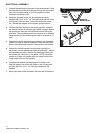
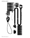
5. Hook each extension spring to the receiving holes on the
pivot beam and attach the opposite end of the spring to its
respective spade bolts. Install the spade bolts through the
extension spring mounting angle on the top rear of the blade.
Secure spade bolts with a 5/8" flat washer and a 5/8"-11
nylock nut. Tighten each nut until a piece of paper can pass
between the 3rd & 4th coils on the spring.
6. Install the blade guides at each end of the moldboard. Insert
the capscrew through the holes at the top of the wing
reinforcement rib. Tighten all screws with lock nuts.
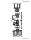
7. Assemble the A-Frame.
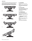
Skid Steer Adapters
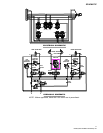
Feed each group of hoses, 2 per side,
through the grommets in the pivot beam.
Positioning the hoses through the pivot
beam supports the hoses while in use and
prevents them from dragging on the ground.
9
16
9
16
60005
60007
9
16
9
16
60272
9
16
9
16