


P.6 Installation Guide AS-6205 SH
“under crank”.
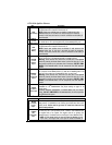
3
GRAY
(-) Hood
Switch
input
Connect this wire to the Hood Pin-switch supplied. This input will disable or
shut down the Remote Starter when the Hood is opened. It is also used for
programming and therefore it is essential that it is installed.
4
ORANGE
(+) Brake
Switch
input
This wire must be connected to the Brake Light switch of the vehicle. The
wire should be +12 V only while the Brake Pedal is pressed. This input will
shut down the Remote Starter if the Brake Pedal is pressed. It is also used
for programming and therefore it is essential that it is installed.
5
YELLOW
+12 V
Parking
Light
output
This wire provides a +12 V output (15 A max.) and must be connected to
the Parking Light wire that tests +12 V when the Parking lights are
ON.
Note: Ensure that the voltage does not vary when the dimmer control
switch is turned up or down. If this is the case, it is not the right wire.
There is also a negative Parking Light output. Only one of these
two different outputs needs to be connected.
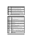
12-Pin Accessories Harness
Wire Description
1
BLUE
(–) AUX 3
(Trunk)
output
500 mA negative output. This output can be used to control Trunk
release (1-sec. pulse) or can be set to operate as a constant output as
long as the
TRUNK button is held pressed. (For Sunroof or Window
close).
Note:
AUX3 (TRUNK) operates only when Ignition is OFF or when the
vehicle is running under remote control.
2
BROWN
(–) Lock
output
Programmable 500 mA, 1/10-sec., 7/10-sec. or 4-sec. negative output.
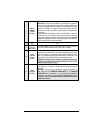
3
GREEN
(–) Unlock
output
Programmable 500 mA, 1/10-sec., 7/10-sec., 4-sec. or a double ¼-sec.
pulse negative output.
4
WHITE /
BROWN
(–) Arm
output
500 mA ground output when the LOCK button is pressed. This output is
activated 500 ms before the
LOCK pulse and deactivated 250 ms after
the
LOCK pulse ends.
Note: The system will also give an
ARM/REARM pulse on this wire when it
shuts down the vehicle after a remote start.
5
WHITE /
GREEN
(–) Disarm
output
500 mA ground output when the UNLOCK button is pressed. This wire is
for disarming OEM Alarm systems.
Note: System will also give a
DISARM pulse before remote start.
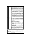
6
BLUE /
WHITE
(+) Positive
Door input
This input should be used in vehicles that use a positive-switching
Dome Light circuit. Connect to a Dome Light wire testing +12 V with a
Door open.
CAUTION! You can only use a negative or a positive connection. In
other words, only the NEGATIVE DOOR INPUT or the POSITIVE
DOOR INPUT wire is connected. It is essential that the Module be
connected in such a way as to allow each one of the Doors to turn off
Ready Mode: the driver-side Door Pin does not constitute by itself a
sufficient connection