


AS-6205 SH Installation Guide P.5
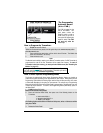
6-Pin Main Ignition Harness
Wire Description
A
RED
+12 V Battery
Connect to the largest 12 V supply wire at the Ignition harness. Ensure that
the OEM power wire is fused for more than 30 A.
NOTE: certain new vehicles have no suitable 12 volts source at the
IGNITION switch (the 12 Volt wire is too small to supply the necessary
current). In this case, the fuse box, or the B+ connection on the battery is
recommended.
B
PURPLE
(+) 30 A
starter output
Connect to the Starter wire of the vehicle (at the IGNITION switch). The source
wire should have +12 V with the Ignition Key in the
CRANK position only.
C
RED
(+) 12 V
Battery
Connect to the largest 12 V supply wire at the Ignition harness. Ensure that
the OEM power wire is fused for more than 30 A.
NOTE: certain new vehicles have no suitable 12 volts source at the
IGNITION switch (the 12 Volt wire is too small to supply the necessary
current). In this case, the fuse box, or the B+ connection on the battery is
recommended.
D
YELLOW
(+) 30 A
ignition
output
Connect to Ignition wire of the vehicle. The source wire should have +12 V
with the Ignition Key in the
IGNITION ON (RUN) and CRANK positions.
Warning: some vehicles have more than one IGN wire at the IGNITION
switch for powering the heater blower motor. Use the 5th relay (pin F) and
extra relays to power up any extra IGN. wires if necessary. DO NOT JUMP
WIRES at the IGNITION switch, this will compromise the OEM electrical
system.
E
ORANGE
(+) 30 A
Accessories
output
This wire is for powering the heater blower motor. It is usually classed as an
ACC. (no power in the CRANK position.) if it tests as an IGNITION (power in the
crank pos.) then power it as an
IGNITION (5th relay, or extra fuse).
Warning: some vehicles have more than one ACC wire at the IGNITION
switch for powering the heater blower motor. Use the 5th relay (pin F) and
extra relays to power up any extra ACC. wires if necessary. DO NOT JUMP
WIRES at the IGNITION switch, this will compromise the OEM electrical
system.
F
GREEN
(+) 30 A 5
th
relay output
This high-current output can be used to power a 2
nd
IGNITION or a 2
nd
ACCESSORY or a 2
nd
STARTER WIRE. See jumper settings on page 16 for
correct output.
Additional IGNITIONS, ACCESSORIES, or STARTER WIRES must use external
relays. DO NOT JUMP WIRES at the IGNITION switch, this will compromise
the OEM electrical system.
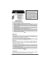
5-Pin Secondary Harness
Wire Description
1
BLACK
(–) Chassis
ground
input
This wire must be connected to bare, unpainted metal (the Chassis or true
Body ground). It is preferable to use a factory ground bolt rather than a self-
tapping screw. Screws tend to get loose or rusted over time and can
cause erratic problems.
2
PURPLE
(AC)
Tachometer
input
This wire tells the Module if the Engine is running or not. It requires at least
1.8 volts (AC) and 1.5 Hz (or faster) at idle. Common Tach references are:
the negative side of an injector, the negative side of an Ignition Coil,
Camshaft sensor, Crankshaft sensor or the Engine Control Module (ECM).
NOTE: A Tach signal that is too low will cause the Module to “over
crank” and a Tach signal that is too high will cause the Module to