


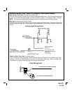
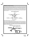
BLUE Wire: Ignition 1 Output
Connect this wire to the ignition 1 wire from the ignition switch. This wire will show +12 volts when the
ignition key is turned to the to the "ON" or "RUN" and the "START" or CRANK" positions, and will have
0 volts when the key is turned to the "OFF" and "ACCESSORY" positions.
For Diesel Applications, this wire must be connected to the ignition circuit that powers the glow plugs if
the vehicle requires glow plug pre-heating. (See selectable feature #9)
GREEN Wire: Ignition 2 Output
Connect this wire to the ignition 2 wire from the ignition switch. This wire will show + 12 volts when the
ignition key is turned to the "ON" or "RUN" position and is some cases the "START" or CRANK" position.
This wire will show 0 volts when the key is turned to the "OFF" and "ACCESSORY" positions.
NOTE: See programming information concerning this wire to allow output during the "START" mode.
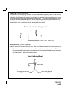
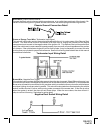
VIOLET Wire: Accessory Output
Connect this wire to the Accessory wire from the ignition switch. This wire will show + 12 volts when the
ignition switch is turned to the "ACCESSORY" or "ON" and "RUN" positions, and will show 0 volts when
the key is turned to the "OFF" and "START" or "CRANK" positions.
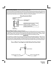
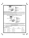
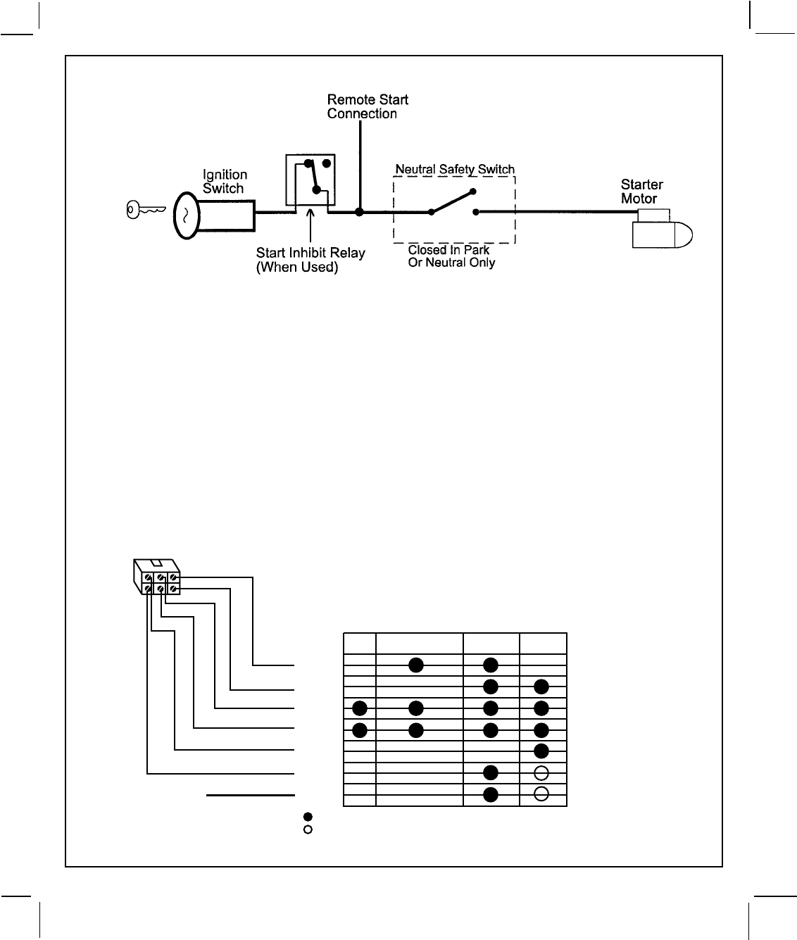
Yellow Start Wire Detail
5
128-5371
5of22
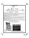
Wiring The 6-Pin Main Power Harness
OFF
ACCESSORY ON/RUN START
+ 12 VOLTS IN SWITCH POSITION INDICATED
MAY BE + 12 VOLTS IN SWITCH POSITION INDICATED
* THIS CIRCUIT IS NOTALWAYS REQUIRED FOR INSTALLATION
ACC
IGN 1
BAT 2
BAT 1
START
IGN 2
*IGN 3*
SEE *WIRING THE
ACCESSORY CONNECTOR
LT. BLUE WIRE
P
U
R
P
L
E
B
L
U
E
R
E
D
R
E
D
/
W
H
I
T
E
Y
E
L
L
O
W
G
R
E
E
N