


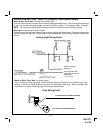
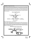
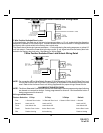
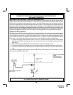
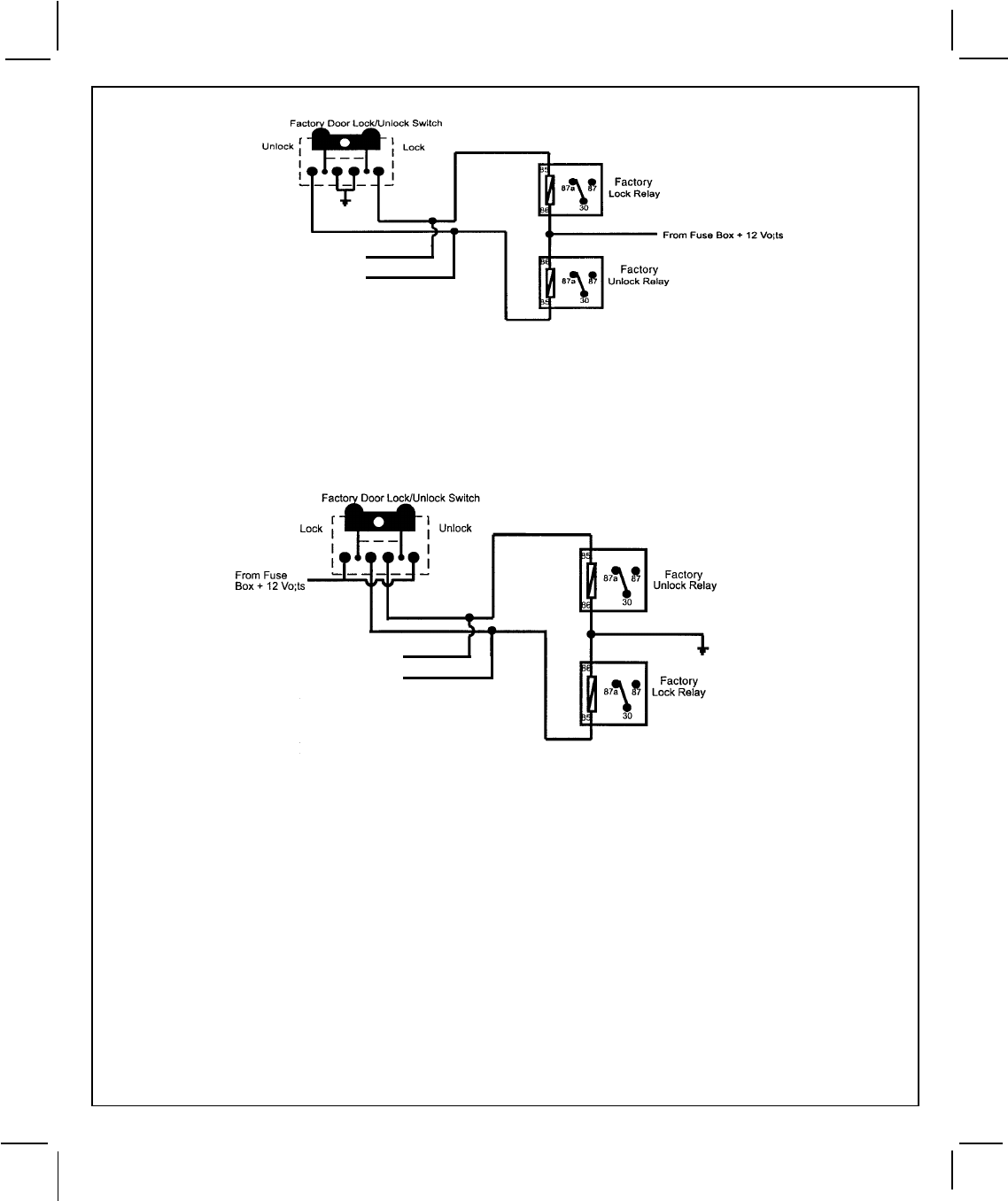
3 Wire Positive Switched Door Lock/Unlock Wiring Detail
14
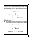
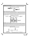
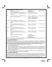
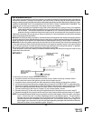
3 Wire Ground Switched Door Lock/Unlock Wiring Detail
128-5371
14 of 22
To Red Lock Wire
Of Control Module
To Green Unlock Wire
Of Control Module
3 Wire Positive Switched Door Locks:
In this application, the Red wire of the two pin harness providesa+12volt pulse during the disarming
sequence, or pulsed 12 volt unlock output. Connect the Red wire to the low current 12 volt signal wire from
the factory door unlock switch to the factory door unlock relay.
The Green wire of the two pin harness providesa+12volt pulse during the arming sequence, or pulsed 12
volt lock output. Connect the Green wire to the low current 12 volt signal wire from the factory door lock
switch to the factory door lock relay. See Below For Wiring Detail.
To Red Unlock Wire
Of Control Module
To Green Lock Wire
Of Control Module
NOTE: For connection to Four Wire Polarity Reversal, 5 Wire Alternating 12 Volts, And All Other Door Lock
Circuits the Audiovox AS-9159 Door Lock Interface, (or equivalent 30 A automotive relays) must be
used. Refer to the Audiovox Door Lock Wiring Supplement for proper wiring of these circuits.
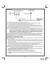
ALARM SELECTABLE FEA TURES
NOTE: The Alarm Selectable Features and Remote Start Selectable Features programming steps following
are based on transmitter button 1 being programmed for channel 1 and transmitter button 2
being programmed for channel 2.
RF Programmable Features:
Feature Selection 1 Chirp 2 Chirp 3 Chirps Default
First 1 Second Door Locks 3.5 Second Door Lock 1 Second L/Dbl. Unlock 1 Second
Second Auto Lock On Auto Lock Off Auto Lock Off
Third Auto Unlock On Auto Unlock Off Auto Unlock Off
Fourth Passive Door Locks Active Door Locks Active Door Locks
Fifth Passive Arming Active Arming Passive Arming