


Typically this output will be used to re-lock the vehicle doors if the doors unlock automatically when the
ignition circuit transitions to off.
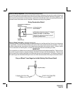
Black w/ Yellow Trace Wire: Ground Output During Start (Crank)
The Black w/ Yellow Trace wire will provide a 300 mAground output while the starter output of the remote
start unit is active. This output can be used to activate the Crank Low/Bulb Test wire found in some GM
vehicles. This wire is also referred to as the ECM wake up wire in some Chrysler vehicles.
NOTE: The outputs above are low current outputs and must be used with a relay if the circuit's
requirement is more than 300mA.
2 Pin Control Switch: (Red Connector)
The Black & Black w/White Trace wires loaded in the two pin red connector enable the operation of the
Remote Start unit. When the Black w/ White Trace wire is grounded, the remote start unit is operable.
When this wire is open from ground, the remote start is disabled. Route the twin lead Black & Black w/
White Trace wires from the control switch to the remote start unit and plug red two pin connector into the
mating red two pin connector shell of the control module.
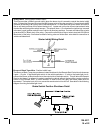
4 Pin Shock Sensor: (White Connector)
The Red (+12 volt), Black (ground), Blue (pre-detect) and Green (full trigger when armed) wires loaded into
the white connector shell are the inputs/outputs of the shock sensor. Route the 4 wire harness from the
shock sensor to the remote start control unit and plug the 4 pin white connector into the mating 4 pin
connector shell of the control module. Note: While operating under the control of the remote start unit the
shock sensor will beshunted (by-passed). Once the remote startshuts down, the shock sensor willbe re-enabled.
2 Pin LED Harness: (White Connector)
The Red & Blue wires loaded into the two pin mini white connector control the anode and cathode of the
dash mounted LED. Route the twin lead Red and Blue wires from the LED to the remote start control unit
and plug the two pin connector into the mating white mini connector shell of the control module.
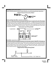
2 Pin Valet/Program Switch: (Blue Connector)
The Black & Grey twin lead wires loaded in the two pin blue connector are the ground supply and program/
valet input of the Remote Start unit. When the Grey wire is grounded, under certain conditions, the unit will
enter the valet mode. When the Grey wire is sequentially grounded under other conditions, the unit will
enter the various program modes. Route the twin lead Black and Grey wires from the valet/Program switch
to the remote start unit and plug the two pin connector into the mating blue connector shell of the control
module. Refer to the remote programming, feature programming and function programming shown later in
this installation guide for operation of the valet/program switch.
3 Pin Antenna/Receiver Connector:
Plug the previously routed three pin connector from the antenna receiver assemble into the mating connec-
tor of the control module. This connector supplies 12 volts, ground and RF data from the antenna receiver
to the remote start module. Be certain this connector is firmly seated making good contact to the control unit.
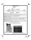
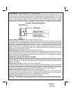
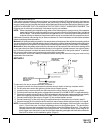
2 Pin Door Lock/Unlock Harness: (White Connector)
The Red & Green Door Lock/Unlock output wires provide either a pulsed ground or pulsed + 12 volts to
control the vehicle door lock / unlock circuits. The output of these wires has a maximum switching
capability of 300mA. Many vehicles today have factory door lock relays which can be connected directly
to these outputs, however always confirm that the factory relays in your particular vehicle do not exceed
the rated 300mA output of the units door lock/unlock circuit. Plug the two pin connector of the door lock/
unlock harness into the mating connector shell of the control module. Determine the door lock circuit of
the vehicle you are working on and wire according to the diagrams shown.
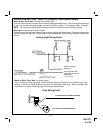
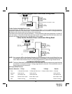
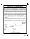
3 Wire Ground Switched Door Lock Circuits:
In this application, the Red wire of the two pin harness provides a ground pulse during the arming se-
quence, or pulsed ground lock output. Connect the Red wire to the low current ground signal wire from the
factory door lock switch to the factory door lock relay.
The Green wire of the two pin harness provides a ground pulse during the disarming sequence, or pulsed
ground unlock output. Connect the Green wire to the low current ground signal wire from the factory door
unlock switch to the factory door unlock relay. See Below For Wiring Detail.
13
128-5371
13 of 22