


6
PLUG-IN CONNECTIONS AND COMPLETING THE INSTALLATION:
Now that all the other components have been installed, and most of the main connections completed, it is
time to finish connecting the remaining plug-in components and completing the installation. Even though
these are plug-in connections, and the plugs have been shaped such that they cannot be plugged in
wrong, please read and follow the instructions below for each connection to make certain each component
is properly installed.
DASH MOUNTED LED
2-PIN White Plug w/2 Wires; Red & Blue
The Red & Blue wires in the 2-PIN mini white connector control the anode and cathode of the dash
mounted LED. Route the twin lead Red and Blue wires from the LED to the control unit and plug the two
pin connector into the mating white mini connector shell of the control module. Do not force the connector,
it will only plug in one way.
OPTIONAL SHOCK SENSOR
4-PIN White Plug w/4 Wires; Red, Black, Blue, & Green
The Red (+12 volt), Black (ground), Blue (pre-detect) and Green (full trigger when armed) wires loaded
into the white connector shell are the inputs/outputs of the shock sensor. Route the 4 wire harness from
the shock sensor location to the EX-6000 Control Module and plug the 4-PIN white connector into the
mating 4-PIN connector.
VALET/PROGRAM/MANUAL OVERRIDE SWITCH
2-PIN Blue Plug w/2 Wires; Black & Gray
The Black & Gray wires in the 2-PIN blue connector are the ground supply and Valet/Program input of the
EX-6000 unit. When the Gray wire is grounded, under certain conditions, the unit will enter the valet
mode. When the Gray wire is sequentially grounded under other conditions, the unit will enter the various
program modes. Route the Black and Grey wires from the Valet/Program/Manual Override switch to the
EX-6000 unit and plug the blue 2-PIN connector into the mating blue connector shell of the EX-6000
control module. Do not force the connector, it will only plug in one way. Note: Please refer to the section;
"Programming System Features" shown later in this installation guide to learn the operation of the valet/
program/manual override switch.
POWER DOOR LOCK HARNESS
2-PIN White Plug w/2 Wires; Red & Green
The connection of the power door lock/unlock wires has already been explained. Route the Red and
Green wires to the EX-6000 unit and plug the white 2-PIN connector into the mating white two pin con-
nector shell of the EX-6000 control module. Do not force the connector, it will only plug in one way.
TRANSMITTER PROGRAMMING:
The transmitters supplied with the EX-6000 are pre-programmed at the factory to provide the following function:
Lock/unlock Button, pressed and released quickly = Arm/Disarm (Lock & Unlock) w/Siren Chirps
Lock/unlock Button, pressed for ~ 1 second = Arm/Disarm (Lock & Unlock) w/o Siren Chirps
Lock/unlock Button, pressed for ~ 3 seconds = Engage/Disengage Panic Mode
Option 1, pressed for ~ 3 seconds = Channel 2 Output
If you desire to have the transmitters operate differently from this factory configuration, please refer to the
separate Transmitter Programming Guide that came with the EX-6000 system.
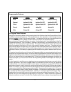
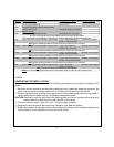
PROGRAMMING FEATURES:
There are five (5) Programmable Features on the EX-6000 system. Study the list below, keeping in mind
the features and their defaults, (how it comes programmed from the factory), and decide how best to
program the EX-6000 for your particular installation.