


5
to the start (crank) position and will have 0 volts in all other key positions.
Connect one side of the cut wire to terminal #87a of the relay. Connect the other side of the cut wire to
terminal #30 of the relay.
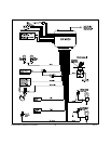
DARK BLUE Wire: Delayed 300mA Pulsed, Channel 2 Output
The Dark Blue wire supplies a 300mA ground pulsed output whenever channel two of the receiver is
accessed. Pressing transmitter Option 1 Button for three seconds will access Channel 2. This is a low
current output and must be connected to a relay to supply power to the trunk release or the circuit you wish
to control. Connect the Dark Blue wire to terminal # 86 of a VF45F11 P&B relay or equivalent. Connect
terminal # 85 of the relay to a fused +12VDC source. Connect the common, normally open, and normally
closed contacts of the relay to perform the selected function of Channel 2.
DOOR LOCK/UNLOCK CONTROL HARNESS (+) and (-)
2-PIN White Plug w/2 Wires; RED & GREEN
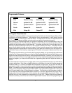
The Red and Green Door Lock/Unlock output wires provide either a momentary pulsed ground (-) or a
momentary pulsed 12VDC (+) output for controlling a vehicle's power door lock/unlock circuit. In order to
accomplish this "dual polarity" output scheme these two wires produce the opposite polarity at the oppo-
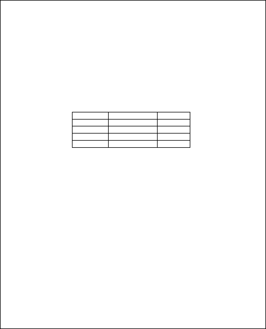
site time. To better understand this, refer to the table below:
The output of these wires has a maximum switching capability of 300mA. Many vehicles today have
factory door lock relays which can be connected directly to these outputs, however always confirm that the
factory relays in your particular vehicle do not exceed the rated 300mA output of the units door lock/unlock
circuit. Plug the two pin connector of the door lock/unlock harness into the mating connector shell of the
control module. Determine the door lock circuit of the vehicle you are working on and wire according to the
diagrams shown.
WIRING FOR "GROUND PULSE" DOOR LOCK CIRCUITS:
This is a system commonly used on most import vehicle's factory door lock/unlock systems, and with a
few domestic vehicles which employ factory "keyless entry" systems. In this application, the Red wire
serves as the "Lock" output, providing a ground pulse during the arming sequence, and the Green wire
serves as the "Unlock" output, providing a ground pulse during the disarming sequence.
Connect the Red wire to the low current ground factory door "Lock" signal wire leading from the factory
switch to the factory door lock relay. Connect the Green wire to the low current ground factory door
"Unlock" signal wire leading from the factory switch to the factory door unlock relay.
WIRING FOR "POSITIVE PULSE" DOOR LOCK CIRCUITS:
This is a system commonly used on many domestic vehicle's factory door lock/unlock systems, particularly
General Motors and Chrysler, although not on all models. (Please see the note regarding "5-Wire Reverse
Polarity Door Lock Systems"). In this application, the Green wire serves as the "Lock" output, providing a
positive pulse during the arming sequence, and the Red wire serves as the "Unlock" output, providing a
positive pulse during the disarming sequence.
Connect the Green wire to the low current positive (+12VDC) factory door "Lock" signal wire leading from
the factory switch to the factory door lock relay. Connect the Red wire to the low current positive (+12VDC)
factory door "Unlock" signal wire leading from the factory switch to the factory door unlock relay.
4 WIRE POLARITY REVERSAL and 5 WIRE ALTERNATING DOOR LOCK CONTROL CIRCUITS:
In these applications, the Door Lock Interface (or equivalent 30 Amp. automotive type relays) must be used.
Wire Color Function Polarity
Red Lock Ground (-)
Red Unlock Positive (+)
Green Lock Positive (+)
Green Unlock Ground (-)