


3
area that may be seen from the driver’s seat as well as from outside the vehicle. Try to choose a location
close enough to the Control Module so that the LED's wires will reach. Carefully inspect the area behind
your chosen location to insure that the drill will not penetrate any existing factory wiring or fluid lines. Drill
a 1/4" hole and pass the connector end of the LED through the hole, and route the wires toward the
location of the Control Module. Press the LED firmly into place until it is fully seated.
HOOD AND TRUNK PIN SWITCHES:
The pin switch included in this package is intended for protecting the hood or trunk/hatch areas of the
vehicle. In all cases, the switch must be mounted to a grounded metal surface. When the pin switch is
activated, (hood/trunk open), it will supply a ground to the input wire thus activating the alarm. Mount the
switches in the hood or trunk locations away from water drain paths. If necessary, the included bracket
may be used to move the switch away from rain gutters or allow mounting to the firewall behind the hood
seal. In both cases the switch must be set up to allow the hood or trunk door to depress the switch at least
1/4 inch when the hood or trunk is closed and fully extended when the hood or trunk is opened. For direct
mounting, a 1/4 inch hole must be drilled. Carefully check behind the chosen location to insure the drill will not
penetrate any existing factory wiring or fluid lines. Drill a 1/4" hole in the desired location and thread the
pin switch into it using a 7/16" nut driver or deep well socket. If using the mounting bracket, first secure the
bracket to the desired location and secure the pin switch in the pre-threaded mounting bracket hole.
WIRING CONNECTIONS:
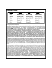
RED Wire (Connects to RED/WHITE wire at harness plug): Main Power Input Wire
These are the main power input wires for the EX-6000 system. Both wires connect to a separate fuseholder
contained in the harness. These fuseholders each hold a separate ATC fuse, one 5AMP and one 15AMP.
This RED wire must be connected to a constant power wire at the vehicle's ignition switch harness or
fusebox. Most vehicles have at least one battery source wire supplying power to the ignition switch.
Locate a constant power wire or power taping point either at the vehicle's ignition switch harness or
fuseblock. This wire will read +12VDC at all times, regardless of the position of the ignition key switch.
Splice and tape the RED wire of the harness to this point.
YELLOW Wire: Ignition Input Wire
This wire provides the EX-6000 system with an ignition power input from the vehicle. Connect this wire to
the primary ignition wire from the ignition switch. This vehicle wire will show +12VDC when the ignition
key is turned to the "ON" or "RUN" position
and
when turned to the "START" or CRANK" positions, and
will have 0VDC when the key is turned to the "OFF" and "ACCESSORY" positions.
Locate an ignition power wire at the vehicle's ignition switch harness. Splice and tape the YELLOW wire
of the system to this point.
WHITE Wire: Positive Parking Light Flash Wire
This wire is designed to provide a +12VDC positive light flash output, driven by the EX-6000's internal
relay, to be connected directly to the vehicle's positive parking light circuit. Once the feedpoint is located,
confirm that all the vehicle's parking lights will illuminate when +12VDC is connected to it.
NOTE:Some vehicles, (mostly European) have isolated "left" and "right" side parking lights. To connect to
the parking light systems in these vehicles, you must use 2 separate SPDT or DPST relays to connect
one to each side in order to keep them isolated.
Locate a parking light feedpoint and attach the WHITE wire of the system to this point.
BROWN Wire: Negative (-) Door Trigger Input Wire
If the vehicle's interior lights are controlled by
grounding
door pin-switches (typical of most GM, Dodge,
and import vehicles), the Brown
negative
door trigger wire should connect to one of the vehicle's factory
door pin switches. In many cases the factory door pin-switches are wired in parallel, making it necessary