


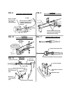
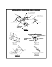

HOW THE CRUISE WORKS
The Cruise Module makes "decisions" based upon speed,tachometer, and brake signal information. The control
circuit interprets digital speed information from the car's engine control module (VSS) or Magnet Kit and ignition
coil output. Brake information comes from the red and purple wires connected to the vehicle's brake switch.
Disengagement and no-engagement decisions are based on the monitored information.
An integral part of the cruise is the 'over rev.' protection circuit. It's function is to monitor engine R.P.M. and
disengage the cruise control when the clutch is applied or the transmission shift lever is moved in to neutral.
When a sudden rise in R.P.M. is detected, the decision to disengage is made for 'over rev' protection, the blue
wire must be attached to the negative side of the ignition coil. A noise suppressor 'in series' with the blue wire
keeps excessive electrical noise from "fooling" the cruise into disengaging. For this reason make sure all cruise
control wiring is at least 1 ft. away from all electromagnetic sources such as: ignition wires, alternator, regulator,
and all high current carrying conductors.
NOTE : If your vehicle is not listed in the enclosed reference manual, the Magnet Kit must be utilized.
Additional available options: CCS-202 Vacuum Reservoir and CCS-204 Ford adaptor.
WARNING : WHEN TESTING WIRES, USE ONLY A LOGIC PROBE OR VOLT / OHM
METER. DO NOT USE A TEST LIGHT, AS THESE CAN CAUSE DAMAGE
TO THE ECM OR MAY ACTIVATE THE AIRBAG!
WARNING : DO NOT ATTEMPT TO ROAD TEST ON JACK STANDS OR A LIFT !
CAUTION : BEFORE DRILLING ANY HOLES, BE SURE THAT NO COMPONENTS
WILL BE DAMAGED AFTER THE DRILL PENETRATES THE SURFACE.
CAUTION : DO NOT MOUNT OR ROUTE WIRING HARNESSES OR KIT COMPONENTS
ON OR NEAR ANY HOT, SHARP, OR MOVING SURFACES WITHIN THE
VEHICLE.
NOTE : IF YOU DO NOT FEEL CONFIDENT THAT YOU CAN SAFELY INSTALL THE
CRUISE CONTROL BY YOURSELF, THEN WE RECOMMEND THAT YOU
HAVE IT INSTALLED BY A QUALIFIED PROFESSIONAL.
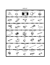
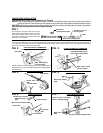
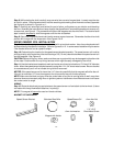
Required Tools
It is important that you read and fully understand this entire instruction manual before proceeding with
the installation. Pay close attention to all cautions and warnings contained in this manual for a safe and
trouble free installation.
4. Pliers
5. Side cutter pliers
6. Small wrench or socket set
1. Digital Volt OHM meter or logic probe
2. Drill with the following size bits : 1/4" & 1/2"
3. #2 Phillips screwdriver
-1-