


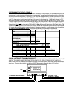
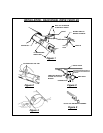

TROUBLE SHOOTING
WIRING - 10 PIN CONNECTOR
Note : If the brown, green, or yellow wires do not test properly, proceed immediately to the testing of the
4 pin control switch testing.
POS WIRE COLOR FUNCTION
9 Black Always continuity to ground
3 Red Always + 12 VDC
1 Brown + 12 VDC with Ignition switch and cruise control switch ON.
O VDC with Ignition switch or cruise control switch OFF.
4 Purple + 12 VDC when the brake pedal is pressed.
0 VDC when the brake pedal is released.
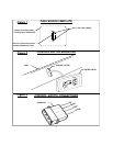
To test the Green and Yellow wires, the Ignition Switch and Cruise Control Switch must both be turned on and
left ON.
8 Green + 12 VDC when the SET / COAST switch is pressed.
0 VDC when the SET / COAST switch is released.
6 Yellow + 12 VDC when the RESUME / ACCEL switch is pressed.
0 VDC when the RESUME / ACCEL switch is released.
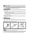
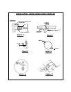
CLOSED CIRCUIT SWITCH
8 Green 0 VDC when the SET / COAST switch is pressed.
+12 VDC when the SET / COAST switch is released.
6 Yellow + 12 VDC when the RESUME / ACCEL switch is pressed.
0 VDC when the RESUME / ACCEL switch is released.
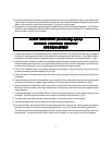
10 Blue Engine RPM. Increasing AC Voltage with engine speed.
2 Grey Vehicle Speed Sensor:
Factory VSS: Roll vehicle forward (approx. 3 feet), in neutral with
Ignition and Cruise Control On. L.E.D. should flash.
Magnets or Fords: Drive at 30 M.P.H. approx. 500-1000 milivolts
AC.
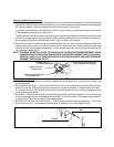
OPEN CIRCUIT SWITCH
4 PIN CONTROL SWITCH TESTING
Red - +12 VDC with Ignition Switch ON.
Brown - Same as Pos 1 above.
Green - Same as Pos 8 above.
Yellow - Same as Pos 6 above.
-11-