


72010 Audiovox Electronics Corporation. All rights reserved.
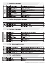
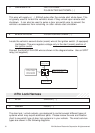
6 GRAY HOOD PIN INPUT ( - )
Install a Hood Pin Switch and connect to the GRAY wire. This connection is
required for Remote Start.
Verification: This wire when connected will register ground when the
vehicle's hood is opened.
Connect the GRAY wire to the hood pin.
NOTE: Be sure to loom the wire, and seal the grommet.
1 BLACK GROUND
Connect the BLACK wire to a solid chassis ground point using a ring terminal and
self tapping screw (not supplied). Scrape away paint from the grounding point to
ensure a good connection. The recommended grounding point is a metal surface
in the driver’s side kick panel area.
NOTE: Do not ground the BLACK wire with any other vehicle components.
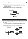
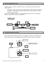
3 Pin Parking Light Harness
7 BROWN/RED BRAKE INPUT ( + )
Locate the vehicle’s brake light wire at the brake pedal mounted switch.
Verification: This wire registers positive voltage when the brake pedal is
pressed.
Connect the BROWN/RED wire to the vehicle’s brake light wire.
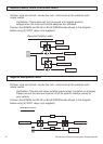
2 WHITE/RED PARKING LIGHT INPUT
3 WHITE PARKING LIGHT OUTPUT
Locate the parking light output wire at the vehicle’s light switch.
Verification: This wire registers positive voltage when the parking lights are
turned on.
Positive switching Parking Lights:
Connect the WHITE/RED wire to a 15 Amp max fused battery source.
Connect the WHITE wire to the parking light output wire.
Negative switching Parking Lights:
Connect the WHITE/RED wire to a good chassis ground.
Connect the WHITE wire to the parking light output wire.