


6 2010 Audiovox Electronics Corporation. All rights reserved.
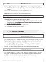
5 PURPLE/WHITE TACH INPUT
Locate the vehicle’s ignition coil or fuel injector in the engine compartment.
Verification: Test using the following procedure:
1. Set voltmeter to AC VOLTS.
2. Attach positive lead of a volt meter to a constant 12-volt source.
3. Attach negative lead of a volt meter to the wire to be tested.
4. Start the engine.
5. Have someone press on the gas pedal slightly as you monitor the meter. If
connected to the correct wire, the voltage reading will increase as the engine’s
RPM increases.
Connect the PURPLE/WHITE wire to the negative side of the vehicle ignition coil
or fuel injector.
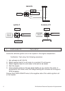
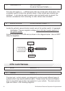
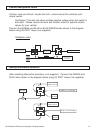
Fused +12 Volt
Battery Source
30
87
87a
86
85
BLUE/BLACK ActiveOutput
Wire
VATS Control Module
Matching Value
Resistor
Ignition Switch
VATS Wire #1, WHITE or WHITE/BLACK
VATS Wire #2, WHITE or VIOLET/WHITE
X CUT
GM VATS
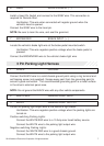
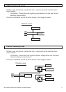
Fused +12 Volt
Battery Source
30
87
87a
86
85
BLUE/BLACK Active Outpu
t
Wire
To Vehicle's 2nd or
3rd Ignition Wire
Jump To PINK
Ignition Output
Wire From
Control Module
Ignition 3 Accessory 2/3
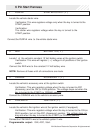
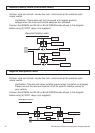
Fused +12 Volt
Battery Source
30
87
87a
86
85
BLUE/BLACK Active Outpu
t
Wire
To Vehicle's 2nd or 3rd
Accessory Wire
Jump To ORANGE
Accessory Output
Wire From
Control Module