


132010 Audiovox Electronics Corporation. All rights reserved.
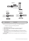
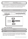
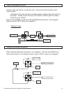
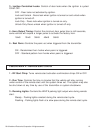
Positive Multiplexed Locks
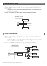
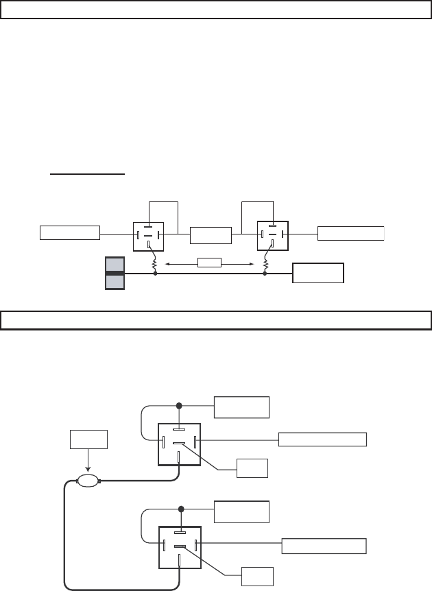
All Door Lock and Unlock: Locate the lock / unlock wire at the vehicle’s lock /
unlock switch.
Verification: This wire will show variable positive voltage when the switch is
activated. Please consult the wire and location chart for specific resistor
values for your vehicle.
Connect the GREEN and BLUE or BLUE/GREEN wires shown in the diagram
below using (2) SPDT relays (not supplied).
Lock
Unlock
Vehicle Door Lock
Control Relays
GREEN (-) Lock Output
BLUE (-) Unlock Output
Multiplex Locks:
87
87a
86
30
87
87a
86
30
85
85
Fused +12 Volt
Battery Source
Resistor
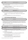
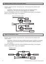
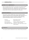
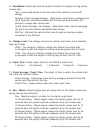
Adding Aftermarket Actuators
After installing aftermarket actuators, (not supplied). Connect the GREEN and
BLUE wires shown in the diagram below using (2) SPDT relays (not supplied).
30
87
87a
86
85
Fused +12 Volt
Battery Source
Door Lock
Actuator
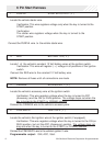
30
87
87a
86
85
Chassis
Ground
Chassis
Ground
GREEN (-) Lock Output
BLUE (-) Unlock Outpu
t
Fused +12 Volt
Battery Source
M