


52010 Audiovox Electronics Corporation. All rights reserved.
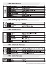
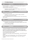
7 Pin Main Harness
1 BLACK/WHITE ILLUMINATED ENTRY OUTPUT ( - )
This wire provides a ( - ) 500mA output for 30 seconds when the system is
disarmed capable of driving relays.
Locate the vehicle’s dome light or pin switch wire.
Verification: This wire will register positive voltage or ground when the
vehicle's dome light is turned ON.
2 BROWN/BLACK HORN OUTPUT ( - )
Locate the vehicle’s horn wire.
Verification: This wire will register at positive voltage and register
ground when the horn switch is pressed.
Connect the BROWN/BLACK wire to the vehicle’s horn wire. This is a low current
output, 500mA.
3 RED/WHITE TRUNK RELEASE OUTPUT ( - )
Locate the vehicle’s trunk release wire at the trunk release switch.
Verification: This wire will register either positive voltage or ground when
the trunk release is activated.
This is a low current output, 500mA.
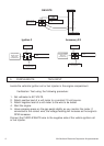
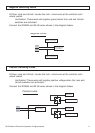
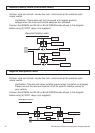
4 BLUE/BLACK IGNITION 3 / ACTIVE OUTPUT ( - )
The Active Output/Ignition 3 output wire provides a ground output when the remote
start function is activated and remains until 4 seconds after the remote start is
shutdown. The Ignition 3 output wire can be used for several functions listed
below. If this wire will be used for multiple application's a 1 amp diode is required
in-line with the stripe facing the control module.
Factory transponder (coded key) bypass.
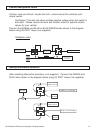
General Motors VATS bypass, see the following diagram. Use an SPDT relay (not
supplied).
Ignition 3 output, see the following diagram. Use an SPDT relay (not supplied).
Accessory 2/3 output, see the following diagram. Use an SPDT relay (not
supplied).