


10 2010 Audiovox Electronics Corporation. All rights reserved.
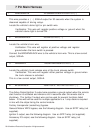
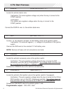
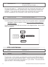
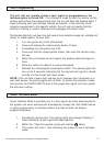
4 BLACK/YELLOW PULSE DURING CRANK ( - )
Locate the vehicle’s second starter (crank) wire at the ignition switch. (if equipped)
Verification: This wire registers voltage only in the start (crank) position of
the ignition switch.
Connect the BLACK/YELLOW wire as shown in the diagram below. Use an SPDT
relay (not supplied).
Fused +12 Volt
Battery S ource
30
87
87a
86
85
BLACK/YELLOW Pulse
During Crank Wire
To Vehicle's2nd
Starter Wire
Jump To PURPLE
Starter Output
Wire From The
Control Module
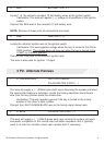
2 Pin Lock Harness
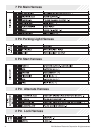
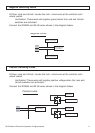
1 BLUE UNLOCK ( - )
2 GREEN LOCK ( - )
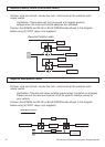
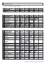
The door lock / unlock outputs are designed to control several different types of
systems which may require additional parts. Please review the wire and location
chart to see which type of door lock system is in your vehicle. The most common
types are shown in the following diagrams.
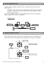
3 GREEN/WHITE FACTORY ARM /
PULSE AFTER SHUTDOWN ( - )
This wire will supply a ( - ) 500mA pulse after the remote start shuts down. This
is typically used to re-lock the vehicle’s doors if they unlock upon remote start
shutdown. It can also be used to pulse a door pin-switch wire to prevent the
vehicle’s accessories from remaining on after remote start shutdown.