


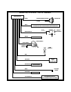

3 Wire Ground Switched door locks
In this application, the red wire provides a ground pulse or the pulsed ground lock output. Connect the red wire to the
wire that provides a low current ground signal from the factory door switch to the factory door lock control relay.
In this application, the green wire provides a pulse ground unlock output. Connect the green wire to the wire that
provides a low current ground signal from the factory door switch to the factory door unlock control relay.
3 Wire Positive Switched Door Locks
In this application,the red wire provides apulsed +12 volt unlock output.Connect the red wire to the wire thatprovides
a low current positive signal from the factory door switch to the factory door unlock control relay.
The green wire provides a positive pulsed +12 volt lock output. Connect the green wire to the wire that provides a low
current positive signal from the factory door switch to the factory door lock control relay.
4 Wire Polarity Reversal and
5 Wire Alternating 12 Volt
Door Lock Control Circuits
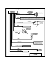
In these applications, the AS 9159 Door Lock Interface ( or equivalent 30 A automotive relays) must be used. Refer
to the AUDIOVOX Door Lock Wiring Supplement for proper connection to these types of circuits.
2 Pin Blue Connector : Programming Switch
Route the grey and black wires in the 2 pin connector from the programming switch to the control module and plug
it into the mating blue connector on the side of the module.
Blue and Green w/Black Trace Wires - 2 Pin White Connector : Accessory Outputs
Dark Blue Wire : Delayed 300 mA Pulsed Output/Channel 2
The dark blue wire pulses to ground via an independent RF channel from the keychain transmitter. This is a
transistorized, low current output, and should only be used to drive an external relay coil.
This output is activated by the same transmitter button that is used to activate the remote start function (factory default
is button 2). Pressand hold button 2 to activate thistrunk release output, or press and release button 2 two times within
2 seconds to activate the remote starter.
WARNING: Connecting the dark blue wire to the high current switched output of the trunk release circuits and some
remote start trigger inputs, will damage the control module.
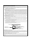
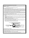
Connect the dark blue wire to terminal 86 of the AS-9256 relay (or equivalent 30 A automotive relay), connect terminal
85 to a fused +12 volt source and wire the remaining relay contacts to perform the selected function of channel 2.
Dark Green w/Black Trace Wire : Latching Output/Channel 3
The green w/black trace wire latches to ground via an independent RF channel from the keychain transmitter. This
is a transistorized, low current (300 mA) output, and should only be used to drive an external relay coil.
This wire provides an immediate ground signal, and stays at ground for up to 8 seconds as long as the button(s) on
the keychain transmitter remain pressed.
WARNING ! Connecting the dark green w/black trace wire to any high current switched output (300 mA max.)
will damage the control module.
Connect the dark green w/black trace wire to terminal 86 of the AS-9256 relay (or equivalent 30 A automotive relay),
connect terminal 85 to a fused +12 volt source and wire the remaining relay contacts to perform the selected function
of channel 3.