


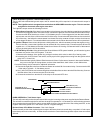
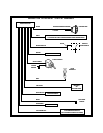
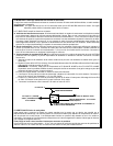
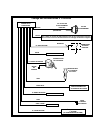
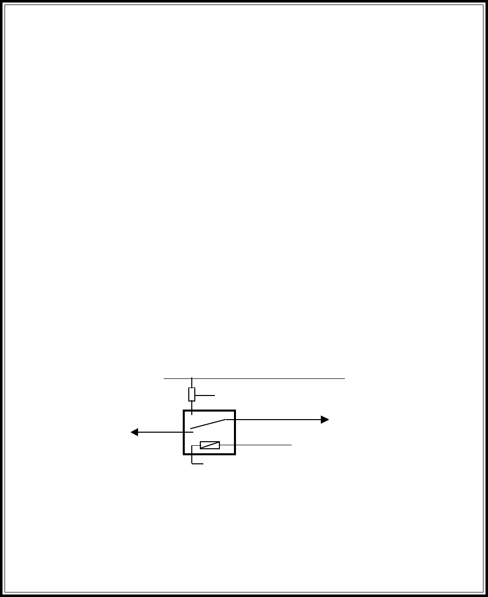
VATS WIRE #1 (CUT)
TOWARDS VATS MODULE
TO FUSED +12 VDC
BATTERY SOURCE
MATCHING RESISTOR
VATS WIRE #1 (CUT)
TOWARDS IGNITION SWITCH
87
87a
85
86
30
VATS WIRE #2
LIGHT BLUE IGN.3 WIRE FROMREMOTE START MODULE
DARK GREEN Wire: Tach Sensor Input
This wire will continually monitor the tach rate while the engine is running under power supplied by the Remote Starter.
This wire will be routed through the fire wall into the engine compartment. It is necessary to use an existing grommet
when passing wires through the fire wall to prevent short circuiting. Connect this wire to the existing tach wire, or the
negative side of the ignition coil in the vehicle. (See RF Program Settings).
Red and Green 2 Pin White Connector : Door Lock Outputs
These wires will provide either a pulsed ground output to the factory door lock control relay, or a pulsed +12 volt output
to the factory door lockcontrol relay. In either case, the maximum current drawthrough these outputs must not exceed
300 mA.
LIGHT BLUE Wire: Ignition 3 / Shock Disable Output
This is a 500 mA transistorized ground output, and an external relay will be required in all cases that this output is
needed.
NOTE: This Light Blue wire is energized 3seconds before the APS-650RSstarts the engine. This wire remains
energized for 4 seconds after engine shut down.
The Light Blue output serves the following functions.
A. Shock Sensor Override:If the alarm is connected to a shock sensor, then the vibration caused by remote starting
the vehicle may trigger the alarm. If this is the case, connect the Light blue wire to terminal 86 of an external relay.
Connect terminal 85 of the relay to a fused + 12 Volt battery source. Cut the trigger wire from the shock sensor,
and connect one side of the cut wire to terminal 30 of the relay. Connect the other side of the cut wire to terminal
87a of the relay. Just before the remote starter is activated, the relay contacts will open, and the shock sensor
will not trigger the alarm. Four seconds after the remote start unit shut down the shock sensor will be operational.
B. Ignition 3 Output: Some newer vehicles use a third ignition wire, which is necessary to keep the engine running.
If this is the case, connect the Light Blue wire to terminal 86 of an external relay. Connect terminals 85 and 30
together toa+12Volt battery source that is fused for a minimum 25 A rating. Connect terminal 87 of the external
relay to the third ignition wire in the vehicle.
C. G.M. VATS Key Override: If the vehicle has the General Motors VATS system installed, you will need to by-pass
the starter cut portion of the VATS system. To do this;
1. Measure the resistance of the ignition key, and get a resistor which value is within 5% of the key value.
2. Locate the pair of VATS wires in the vehicle, usually a pair of thin gauge wires running from the ignition switch
to the VAT 1 Control Unit.
NOTE: These wires are typically White w/ Black tracer and Violet w/ Yellow tracer, however in late model Cadillacs,
they are run through an Orange sleeve, and are either both Black, both Yellow, or both White wires.
Consult the factory service manual for additional information.
3. Connect the Light Blue wire from the Remote Starter to terminal 86 of an external relay. Connect terminal 85
of the relay to a fused + 12 Volt battery source.
4.Cut (1) ofthe VATS wires,and connectthe ignition switchside of thecut wire toterminal 87aof the relay.Connect
the other side of the cut wire to terminal 30 of the relay.
5. Connect the resistor from terminal 87 of the relay to the second VATS wire.