


The APS 650 RS is for Automatic Transmission vehicles only! Although it is a sophisticated system, with multiple built-
in safety features, it must not be installed into vehicles with manual transmissions. Doing this can cause serious
personal injury and property damage.
IMPORTANT ! DO NOT PLUG THE SIX PIN MAIN POWER HARNESS OR THE 12 PIN INPUT / OUTPUT HARNESS
INTO THEREMOTE START CONTROL MODULE UNTIL ALLCONNECTIONS HAVE BEENMADE TO
THE VEHICLE. AFTER SELECTING YOUR TARGET WIRES AS DEFINED BELOW DISCONNECT
THE NEGATIVE BATTERY CABLE FROM THE BATTERY PRIOR TO MAKING ANY CONNECTIONS!
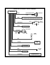
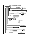
WIRING CONNECTIONS: 6 Pin Main Power Harness
RED w/ WHITE Tracer Wire:+12VDCBattery 1 Source
Connect this wire to a +12 VDC constant source found at the vehicles ignition switch using the 30 A fuse provided.
The Battery 1 sourceprovides +12 voltsto theAPS 650RS module forIgnition 1output, Ignition 2output, andthe circuits
logic.
REDWire:+12VDCBattery 2 Source
Connect this wire toa+12VDCconstant source found at the vehicles ignition switch but NOT the same wire as the
battery 1 source. Most vehicles have multiple+12 VDC batteryfeeds found atthe vehicles ignition switch.Separate feed
wires must be used for the red and red w/white wires. If your vehicle does not provide at least two +12 VDC feed wires,
then it is possible to connectboth wires to thevehicle battery. If connecting tothe vehicle battery alwaysfuse these wires
at the source using the 30 A fuses provided.
The Battery 2 source provides + 12 volts to the APS 650 RS module for Starter output and Accessory output.
YELLOW Wire : Starter Output
Connect this wire to the starter wire from the ignition switch harness. This wire will show +12 Volts when the ignition key
is turned to the “ START or CRANK “ position, and 0 Volts when the ignition key is in any other position.
NOTE: Ifinstalling the APS-650 RSwith an alarm that utilizes a startercut relay, make sure the Yellow wireis connected
to the “ starter “ side of the relay contacts, and not the “ switch “ side.
When installing the APS-650 RS into vehicles with a factory installed security system, connect the Yellow wire between
the output of the starter cut relay and the neutral safety switch.
BLUE Wire : Ignition 1 Output
Connect this wire to the ignition 1 wire from the ignition switch harness. This wire will show +12 Volts when the ignition
key is turned to the “ RUN or ON “ and the “ START or CRANK “ positions, and 0 Volts when the key is turned to the
“ OFF “ and “ ACCESSORY “ positions.
LIGHT GREEN Wire : Ignition 2 Output
Connectthis wireto theignition 2wire fromthe ignitionswitch. Thiswire will show+12 Voltswhen theignition keyis turned
to the “ RUN or ON “ position, and in some cases, the “ START or CRANK “ position. This wire will show 0 Volts when
the key is turned to the “ OFF “ and “ ACCESSORY “ positions.
NOTE: The APS 650 RS ignition 2 output can be programmed to remain ON while the starter is cranking. The factory
default setting for ignition 2 is to show 0 volts while the starter is cranking.
This output should be programmed at time of installation and should simulate the ignition 2 source in the vehicle when
the ignition key is used to start.
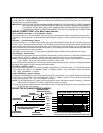
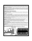
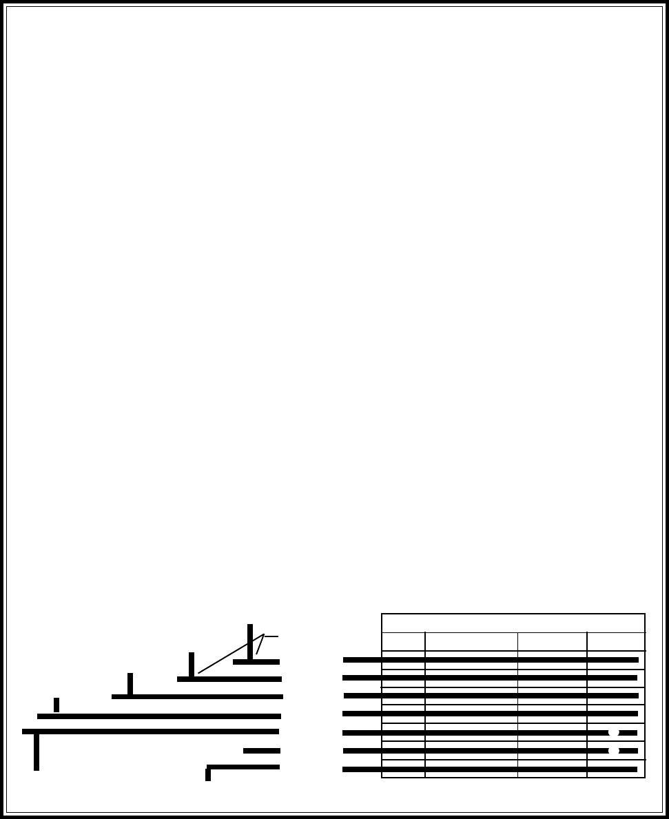
BATT 1
BATT 2
ACC
IGN 1
IGN 2
IGN 3
START
*
IGNITION SWITCH KEY POSITION
OFF ACCESSORY ON / RUN START
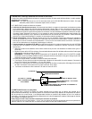
SEE"WIRINGTHE12PINCONNECTOR"-
LT.BLUEWIREIFREQUIRED.
LT.GREENWIRE
FROMAPS650RS
YELLOWWIRE
FROMAPS650RS
MAY BE +12 VDC IN KEY POSITION INDICATED
+12 VDC IN KEY POSITION INDICATED
WIRING THE 6 PIN MAIN POWER HARNESS
LT.BLUEWIRE
FROMAPS650RS
VIOLETWIRE
FROMAPS650RS
REDw/WHITETRACE
WIREFROMAPS650RS
REDWIRE
FROMAPS650RS
SPLICE(TYP.)
THIS CIRCUIT IS NOT ALWAYS REQUIRED FOR INSTALLATION
*