


VIOLET Wire : Accessory Output
Connect this wire to the accessory wire from the ignition switch. This wire will show +12 Volts when the ignition key
is turned to the “ ACCESSORY “ and “ RUN or ON “ positions, and 0 Volts when the key is turned to the “ OFF “ and
“ START or CRANK “ positions.
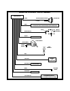
WIRING CONNECTIONS: 12 Pin Input / Output Harness
BLACK Wire: Chassis Ground Source
Connect this wire to a solid, clean chassis ground source.
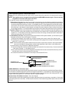
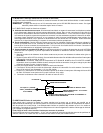
BLACK w/WHITE Tracer Wire: Control Switch
The Black w/ White tracer wire provides ON-OFF control of the Remote Starter.
When the Black w/ White wire is switched to a full time ground, the APS-650 RS Remote Start Module is operative.
When the Black w/ White wire is at open circuit through the control switch, the remote starter is disabled.
Connect the Black w/ White tracer wire to one of the terminals from the back of the control switch. Connect the
remaining terminal on the control switch to chassis ground. Always try to mount the switch so that the ON position
is in an upward direction.
GREY Wire: Negative Inhibit Input 1
Connect the GREY wire to the hood pin switch provided . This wire will be routed through the fire wall into the engine
compartment. It is necessary to use an existing grommet when passing wires through the fire wall to prevent short
circuiting. This is an important safety feature of APS 650 RS, and failure to use this feature can result in serious injury.
In some cases, the bracket provided may be required to facilitate mounting of the hood pin switch.
GREY w/ BLACK Tracer Wire: Negative Inhibit Input 2
Any time the greyw/ black tracerwire is grounded,the RemoteStarter will stopoperating, even ifthe signal isreceived
from the transmitter.
If the brake light switch in the vehicle switches ground to the brake light circuit, connect the Grey w/ Black trace wire
to the output of the brake light switch. If the brake light switch in the vehicle switches +12 Volts, do not use the Grey
w/ Black wire; see Brown w/ Black tracer wire.
BROWN Wire: Positive Inhibit Input 1
Any time + 12 Volts is applied to the Brown wire, the Remote Starter will stop operating, even if the signal is received
from the transmitter.
If the vehicle has a factory installed hood pin switch, and that switch provides + 12 Volts to an under hood light, the
Brown wire can be connected to the existing pin switch.
BROWN w/ BLACK Tracer Wire: Positive Inhibit Input 2
Any time + 12 Volts is applied to the Brown w/ Black tracer wire, the Remote Starter will stop operating, even if the
signalis receivedfrom thetransmitter. Ifthe brakelight switchin thevehicle switches +12 Voltsto thebrake lightcircuit,
connect the Brown w/ Black trace wire to the output of the brake light switch. If the brake light switch in the vehicle
switches ground, do not use the Brown w/ Black wire; see Grey w/ Black tracer wire.
YELLOW w/ BLACK Tracer Wire: + 12 Volt Alarm By - Pass Output
NOTE: YOU MUST DISCONNECT THE IGNITION INPUT OF THE ALARM FROM ANY OTHER WIRE THAT IT IS
PRESENTLY CONNECTED TO IN THE VEHICLE.
This wire provides a 500 mA + 12 Volt transistorized output when the ignition key is turned to the “ON” position, and
0 Volts when the ignition key is “OFF” and when the vehicle is running under the control of the remote starter.
This wire should be connected to the ignition input of the alarm system.
The Yellow w/ Black wire output will allow you to remote start the vehicle while leaving the alarm armed.
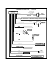
(2) WHITE Wires: Parking Light Flasher
These wires are the COMMON and NORMALLY OPEN contacts of the on-board parking lamp relay.
If the vehicle's parking lights are a +12 volt switched system, connect (1) of the White wires to a fused (15A max.) +12
volt battery source, and connect the second White wire to the vehicle's parking light wire.
If the vehicle's parkinglights area chassisground switchedsystem, connect(1) ofthe Whitewires toa chassisground
source, and connect the second White wire to the vehicle's parking light wire.