


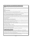

RED FUSED WIRE - (HARDWIRE): + 12 VDC CONSTANT BATTERY SOURCE
Whenhardwiring thecontrol moduleto pinswitches atall entrypoints, thevoltage sensecircuit mustbedisabled. Cutthe greenwire
loop from the alarm control module. Connect the red fused wire toa+12VDCconstant battery source.
YELLOW WIRE: + 12 VDC IGNITION SOURCE
Connect this wire to a source that is hot when the key is in the on, accessory, and crank positions, and off when the key is in the off
position.
BLACK WIRE: CHASSIS GROUND
Connect this wire to a solid, metal part of the vehicle’s chassis.
Do not confuse this wire with the thin black antenna wire that exits the control module independently.
WHITE WIRE: + 12 VDC PULSED PARKING LIGHT OUTPUT ( 15 A MAX )
This wire is provided to flash the vehicle’s parking lights.
Connect the white wire to the positive side of one of the vehicle’s parking lights.
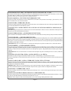
DARK GREEN WIRE: (-) INSTANT TRIGGER
This is an instant on ground trigger wire. It must be connected to the previously installed hood and trunk pin switches.
PURPLE WIRE: + DOOR TRIGGER
If the vehicle’s door courtesy light switches havea+12volt output when the door is opened ( most Fords and some Imports ), you
mustconnectthiswiretothepositiveoutputfromoneofthedoorswitches.Inmostcases,thepurplewirewillonlyneedtobeconnected
to one door switch, no matter how many doors the vehicle has.
WARNING: Do not use the purple wire if the vehicle has ground output type door switches. (see BROWN WIRE)
BROWN WIRE: - DOOR TRIGGER
Ifthevehicle’sdoorcourtesy lightswitcheshavea-groundoutputwhenthedoorisopened (GMandmostImports)youmustconnect
this wire to the negative output from one of the door switches. In most cases, the brown wire will only need to be connected to one
door switch, no matter how many doors the vehicle has.
WARNING: Do not use the brown wire if the vehicle has + 12 Volt output type door switches. (see PURPLE WIRE)
WHITE w/ BLACK TRACE WIRE: POSITIVE OUTPUT TO SIREN
Route this wire through a rubber grommet in the firewall, and to the siren location.
Connect the white/black wire to the positive wire of the siren. Secure the black ground wire of the siren to chassis ground.
ORANGE WIRE: GROUND OUTPUT WHEN ARMED
This wire is provided to control the optional (not included) starter cut relay. Connect the orange wire to terminal 86 of the AS-9256
relay (or equivalent 30A automotive relay), and wire the remaining relay contacts as shown in the wiring diagram.
IMPORTANT: Audiovox does not recommend using this relay to interrupt the ignition wire. Only connect this relay to the
low current starter solenoid feed wire, as indicated on the wiring diagram.
GREY WIRE: VALET SWITCH
Connect the grey wire from the alarm harness to the grey wire from the valet switch. Connect the black wire from the valet switch
to chassis ground.
DARK BLUE w/WHITE TRACER WIRE: L.E.D.
Connect the blue w/white wire from the alarm harness to the blue wire from the dash mounted LED. Connect the red wire from the
dash LED to a fused +12 VDC battery source.
NOTE: Always connect the blue LED wire first. This will prevent permanent damage to the LED.
RED & GREEN 2 PIN CONNECTOR: DOOR LOCK OUTPUTS
These wires will provide a pulsed ground output to the factory door lock control relay.
The maximum current draw through these outputs must not exceed 300 mA.
Page 3