


Page 2
CONTROL MODULE:
Select a mounting location inside the passenger compartment (up behind the dash), and secure using two screws provided.
The control module can also be secured in place using cable ties.
Donot mountthecontrolmodule intheengine compartment,asitis notwaterproof.Youshould alsoavoidmounting theunitdirectly
ontofactoryinstalledelectroniccomponents. ThesecomponentsmaycauseRFinterference,whichcanresultinpoortransmitterrange
or intermittent operation.
SIREN:
Selecta mountinglocationin theenginecompartmentthat iswellprotected fromaccessbelow thevehicle.Avoid areasnearhigh heat
components or moving parts within the engine compartment. To prevent water retention, the flared end of the siren must be pointed
downward when mounted.
Mount the siren to the selected location using the screws and bracket provided.
HOOD OR TRUNK PIN SWITCH:
A pin switch is included for use in protecting the hood or trunk (or hatchback) of the vehicle.
Theswitchmust alwaysbemountedto agrounded,metalsurfaceof thevehicle.Itis importanttoselectalocation wherewatercannot
flow or collect, and to avoid all drip “gutters” on hood and trunk fenderwalls. Choose locations that are protected by rubber gaskets
when the hood or trunk lid is closed.
The pin switch can be mounted using the bracket provided, or direct mounted by drilling a 9/32" diameter mounting hole.
Keepinmindthatwhenproperlymounted,theplungerofthepinswitchshoulddepressatleast1/4"whenthehoodortrunklidisclosed.
DASH MOUNTED L.E.D.:
A smallred L.E.D. isincluded thatwill serve asa visual indicatorof thealarm status. Itshould be installedin thedash, located where
it can be easily seen from outside the vehicle, yet not be distracting to the driver.
Oncealocationhasbeenselected,checkbehindthepanelfor wireroutingaccess,andtoconfirmthedrillwillnotdamageanyexisting
components as it passes through the panel.
Drilla15/64"diameterhole, andpasstheredandbluewiresfromtheL.E.D.through thehole,fromthefrontofthepanel.Firmlypress
the body of the L.E.D. into the hole until fully seated.
VALET SWITCH:
Select a desired mounting location for the switch, that is easily accessible to the driver of the vehicle.
The switch does not have to be concealed, however, concealing the switch is always recommended, as this provides an even higher
levelof securitytothevehicle. Theswitchmay bemountedbelow thedashusingone ofthebrackets provided,ormountedin thedash
by drilling a 1/4" diameter hole in the location. Be sure to check behind the dash for adequate clearance for the body of the switch,
and to confirm that the drill will not damage any existing components as it passes through the dash.
Whichever mounting method is used, make certain the back of the switch is accessible for wiring later in the installation.
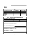
RED FUSED WIRE - (VOLTAGE SENSING): + 12 VDC CONSTANT BATTERY SOURCE
Thiswire controlsthesensitivity ofthevoltage sensingcircuit,which detectstheturning onof aninteriorlight whenadoor isopened.
Itwillalsodetecttheswitchingonofparkingorheadlamps,andinmanycaseswilltriggerthealarmwhenathermostaticallycontrolled
electronic radiator cooling fan switches on.
It is recommended that when installing this system into vehicles with electronic “after fans”, the procedure for RED FUSED WIRE
- (HARDWIRE) should be followed.
Involtagesensingapplications,theclosertothebatterythattheredfusedwireisconnected,thelesssensitivethevoltagesensecircuitry
will be. Moving this connection point to the fuse panel will increase the sensitivity, and connecting to the courtesy lamp fuse in the
vehicle will provide maximum sensitivity of the voltage sense circuit.
WIRING THE SYSTEM:
INSTALLATION OF MAJOR COMPONENTS: