


Page 4
most cases, the purple wire will only need to be connected to one door switch, no matter how many doors
the vehicle has.
WARNING : Do not use the purple wire if the vehicle has ground output type door switches.
( see Brown Wire ).
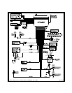
Orange Wire : 300 mA GROUND OUTPUT WHEN ARMED - N. C. STARTER DISABLE
This wire is provided to control the starter cut relay. Connect the orange wire to terminal 86 of the relay.
Connect relay terminal 85 to an ignition wire in the vehicle that is live when the key is in the on and crank
positions, and off when the key is in the off position. ( This is where the yellow wire from the alarm should
be connected ).
Cut the low current starter solenoid wire in the vehicle, and connect one side of the cut wire to relay
terminal 87A. Connect the other side of the cut wire to relay terminal 30.
Note : This is a normally closed starter cut arrangement and when power is removed from the
security system, the starter disable feature will not operate, allowing the vehicle to start.
Audiovox does not recommend using the Orange wire to interrupt anything but the
starting circuit of the vehicle.
Black w/White Trace Wire: LOW CURRENT NEGATIVE HORN OUTPUT (300mA MAX CURRENT)
The Black w/White trace wire provides a 300mA pulsed output to beep the vehicle's horn. This low current
pulsed output should only be connected to the low current switched ground output from the vehicle's horn
switch. If the vehicle switches high current ground or + 12 volts to the horn, a relay must be used to
operate the vehicle horn. Connect the Black w/White trace wire to terminal #86 of a VF45F11 P&B or
equivalent 30A automotive relay. Connect terminal #85 to a fused + 12 volt source. Connect the remain-
ing relay contacts 87, 87a and 30 to perform the switching function the vehicle's horn circuit requires.
Dark Blue w/Black Trace Wire: Alternate Channel 3 Output (Dbl. Push Required)
This wire is controlled from the transmitter button programmed to the receiver's channel 3. By double
pressing this the transmitter button, this output will become active for 1 second. This is a transistorized,
low current ( 300 mA ) output, designed to provide an output only when the transmitter is intentionally
operated, such as is the case with remote start add on modules. If you require more than 300mA drive
from this output, you must drive an external relay coil, and arrange the relays contacts to preform the
specified function.
Dark Green w/ White Trace Wire : Entry Illumination ( 300 mA max. )
The dark green w/ white trace wire provides a 30 second ground signal whenever the system is disarmed,
and pulses ground whenever the system is triggered. It should be used to provide the ( optional ) entry
lighting and to flash the vehicle’s dome light while the alarm is sounding. This is a transistorized, low
current output and should only be used to drive an external relay coil.
Connect the dark green with white trace wire to terminal 86 of the AS - 9256 relay ( or equivalent 30 A
automotive relay ) and wire the remaining relay contacts according to the polarity of the dome light circuit
in the vehicle.
NOTE : When wiring this feature in vehicles with factory equipped delay lighting circuits, it is
best to connect to the output of the timer which feeds the dome light, rather than at the
door switch. This will ensure that the dome light pulses when the alarm is triggered.
Light Green Wire : ( - ) Instant Trigger Zone 1
This is an instant on ground trigger wire. This wire ( zone ) should be reserved for connection to optional
ground output trigger devices such as motion and / or shock impact sensors.
2 Pin Blue Connector : VALET SWITCH
Route the grey and black wires in the 2 pin connector from the valet switch to the control module, and plug
it into the mating blue connector on the side of the module.
2 Pin White Connector : DASH MOUNTED LED
Route the red and blue wires in the 2 pin white connector from the LED to the control module, and plug it
into the mating white connector on the side of the module.
4 Pin White Connector : SHOCK SENSOR
Route the red, black, blue, and green wires in the 4 pin white connector from the shock sensor to the
control module, and plug one end into the shock sensor, and the other end into the mating white
connector on the side of the module.