


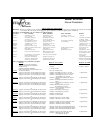

Page 2
or
Eight Press and release the valet switch 2 chirps = horn chirp output 16mS
Press transmitter Lock button to change 3 chirps = horn chirp output 30mS
Press transmitter Lock button to change 1 chirp = horn chirp output 10 mS
or
Ninth Press and release the valet switch 2 chirps = valet switch override operation
Press transmitter Lock button to change 1 chirp = custom code override operation
or
Tenth Press and release the valet switch 2 chirps = 2 step unlock off
Press transmitter Lock button to change 1 chirp = 2 step unlock on
or
Eleventh Press and release the valet switch 2 chirps = chirp delete from transmitter inactive
Press transmitter Lock button to change 1 chirp = chirp delete from transmitter active
Press and release the valet switch Exit program mode
or
Turn ignition key off Exit program mode
Note: Once you enter the feature programming mode, do not allow more than 30 seconds to pass between steps, or the
programming will be terminated.
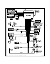
INSTALLATION OF MAJOR COMPONENTS
Control Module :
Select a mounting location inside the passenger compartment ( up behind the dash ), and secure using
the two screws provided. The control module can also be secured in place using cable ties.
Do not
mount the control module in the engine compartment, as it is not waterproof. You should also avoid
mounting the unit directly onto factory installed electronic components. These components may cause RF
interference, which can result in poor transmitter range or intermittent operation.
Siren :
Select a mounting location in the engine compartment that is well protected from access below the
vehicle. Avoid areas near high heat components or moving parts within the engine compartment. To prevent
water retention, the front or sounding end of the siren must be pointed downward when mounted.
Mount the siren to the selected location using the screws and bracket provided.
Hood or Trunk Pin Switch :
A pin switch is included for use in protecting the hood or trunk ( or hatchback ) of the vehicle. The switch
must always be mounted to a grounded, metal surface of the vehicle. It is important to select a location
where water cannot flow or collect and to avoid all drip gutters on hood and trunk fender walls. Choose
locations that are protected by rubber gaskets when the hood or trunk lid is closed.
The pin switch can be mounted using the bracket provided, or direct mounted by drilling a ¼ “ diameter
mounting hole. Keep in mind that when properly mounted, the plunger of the pin switch should depress at
least ¼ “ when the hood or trunk lid is closed.
Dash Mounted LED :
A small red LED is included that will serve as a visual indicator of the alarm status. It should be installed
in the dash, located where it can be easily seen from outside the vehicle, yet not be distracting to the
driver.
Once a location has been selected, check behind the panel for wire routing access and to confirm the drill
will not damage any existing components as it passes through the panel.
Drill a ¼ “ diameter hole and pass the red and blue wires from the LED through the hole, from the front of
the panel. Firmly press the body of the LED into the hole until fully seated.
Valet Switch :
Select a mounting location for the switch that is easily accessible to the driver of the vehicle. The switch
does not have to be concealed, however, concealing the switch is always recommended, as this provides
an even higher level of security to the vehicle.
The valet switch can be mounted to the lower side of the dash by drilling a ¼ “ diameter hole in the selected
location.
Be sure to check behind the dash for adequate clearance for the body of the switch and to confirm that the
drill will not damage any existing components as it passes through the dash. You should also make
certain that the back of the switch is accessible for wiring later in the installation.