


Page 3
Shock Sensor :
Select a solid mounting surface for the shock sensor on the firewall inside the passenger compartment and
mount the sensor using the two screws provided. The shock sensor can also be secured to any fixed brace
behind the dash using tie straps.
Whichever mounting method is selected, make certain that the sensitivity adjustment is accessible for use
later in the installation.
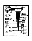
WIRING THE SYSTEM
Large 15 Pin Edge Connector :
White Wire : + 12 VDC PULSED PARKING LIGHT OUTPUT ( 15 AMP MAX )
This wire is provided to flash the vehicle’s parking lights. Connect the white wire to the positive side of one
of the vehicle’s parking lights.
Red Fused Wire : + 12 VDC CONSTANT BATTERY SOURCE
This wire controls the sensitivity of the voltage sensing circuit, which detects the turning on of an interior
light when a door is opened. It will also detect the switching on of parking or headlamps and in many cases
will trigger the alarm when a thermostatically controlled electronic radiator cooling fan switches on.
When installing this system into vehicles with electronic ''after fans'' , it is recommended you disable the
voltage sense circuit.
In voltage sensing applications, the closer to the battery that the red wire is connected, the less sensitive
the voltage sense circuitry will be. Moving this connection point to the fuse panel will increase the sensi-
tivity, and connecting to the courtesy lamp fuse in the vehicle will provide maximum sensitivity of the
voltage sense circuit.
When hardwiring the control module, the voltage sense circuit must be disabled. After wiring of the control
module and connecting the Red wire to a fused battery source, be certain program feature # six is set for
Hardwire.
Dark Blue Wire : DELAYED 300 mA PULSED OUTPUT / CHANNEL 3
The dark blue wire pulses to ground via an independent RF channel from the keychain transmitter. This is
a transistorized, low current output and should only be used to drive an external relay coil.
WARNING: Connecting the dark blue wire to the high current switched output of trunk release circuits,
some remote start trigger inputs, will damage the control module.
Connect the dark blue wire to terminal 86 of the AS - 9256 relay (or equivalent 30A automotive relay) and
wire the remaining relay contacts to perform the selected function of channel 3.
White w/ Black Trace Wire : POSITIVE OUTPUT TO SIREN
Route this wire through a rubber grommet in the firewall, and to the siren location.
Connect the white / black wire to the positive wire of the siren. Secure the black ground wire of the siren to
chassis ground.
Black Wire : CHASSIS GROUND
Connect this wire to a solid, metal part of the vehicle’s chassis. Do not confuse this wire with the thin black
antenna wire that exits the control module independently.
Yellow Wire : + 12 VDC IGNITION SOURCE
Connect this wire to a source that is live when the key is in the on and crank positions. Be sure that this
source is off when the key is in the off position.
Dark Green Wire : ( - ) INSTANT TRIGGER ZONE
This is an instant on ground trigger wire. It must be connected to the previously installed hood and trunk pin
switches.
Brown Wire : - DOOR TRIGGER
If the vehicle’s courtesy light switches have a ( - ) ground output when the door is opened (GM and most
Imports), you must connect this wire to the negative output from one of the door switches.
WARNING : Do not use the brown wire if the vehicle has + 12 volt output type door switches.
( see Purple Wire ).
Purple Wire : + DOOR TRIGGER
If the vehicle’s door courtesy light switches have a + 12 volt output when the door is opened ( most Fords
and some Imports ), you must connect this wire to the positive output from one of the door switches. In